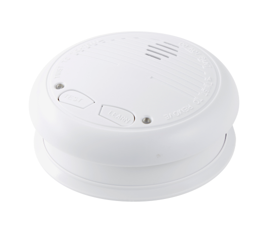
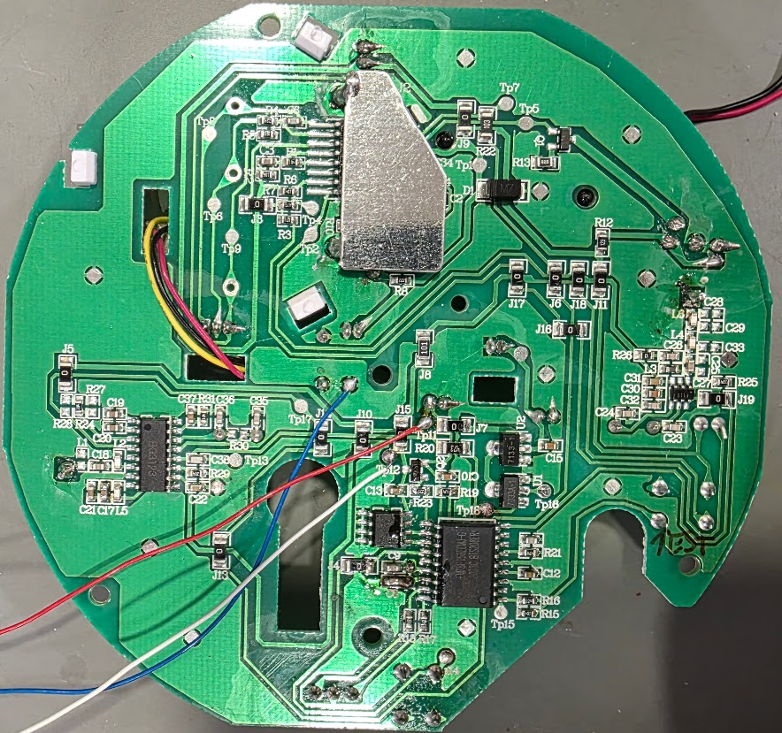
he Chinese brand Kingdunalarm has produced the LM-101LG for years. These detectors have been imported into the EU since at least 2013, often marketed under names like No-Flame and Nor-Tec. It is a reliable, linked optical smoke and heat detector, making it a good candidate for this modification.
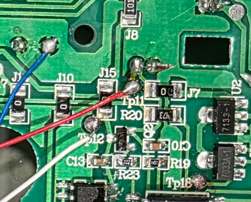
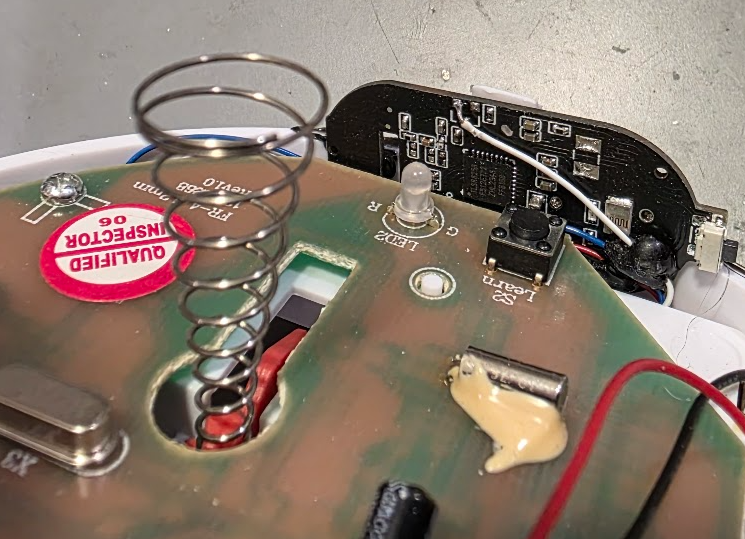
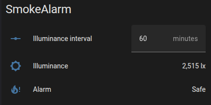
This modification adds Zigbee compatibility, allowing you to receive a notification whenever the alarm sounds. This can be triggered either by its own sensors or by a test button signal forwarded from another linked alarm.
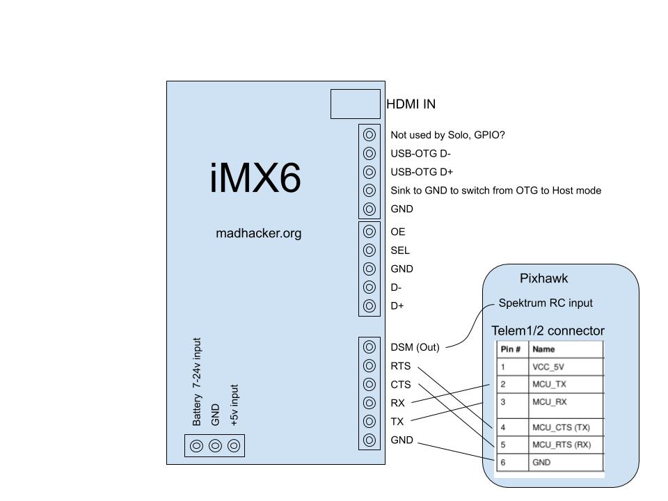
3DR Solo, have a great onboard computer, the IMX6 runs Yocto Linux : link to the Linux source: https://github.com/OpenSolo/imx6-linux
Among it’s best features is the HDMI-in, USB, and mini-PCIe port which can easily use rather powerful MicroTik router/Wi-Fi modules.
I reverse-engineered the remaining pins, as only the 3 and 6 pin headers were known to the community.|
Battery 7-24v, is the main power source. +5v input does not seem to be essential for normal operation. First USB host (D+,D-) is a normal USB2.0 host, compatible. SEL(select) and OE(output enable) are two GPIO pins used by Solo to select where this USB host is connected: During normal operation the OE control if it is connected to any device (or not) and SEL controls if it is connected to the Cube (for firmware upgrade via bootloader) or the gimbal bay connector.
Unless you need more than two USB devices, you can ignore SEL and OE, and just use D+/D- for the USB host as usual.
Then there is the USB-OTG port. If you pull down the “Sink to GND…” pin, then the USB-OTG port becomes another USB host port. Otherwise, the USB-OTG port is in OTG mode, and will act as a slave/device – so that you can connect it directly to another host(usually a computer) This pin is not routed to anything on the Solo main board I tested.
The default onboard Linux is compiled only with FTDI and CDC-ACM (Communication Device Class – Abstract Control Model) profile, so it will instantly work with all kinds of Arduino/STM32’s that normally show up as a ttyUSB or ttyACM device.
DSM outputs a Spektrum RC control signal from the Solo Controller, it is optional to use it.
Finally, there is the usual RTS, CTS, RX, TX that is used for MAVLink telemetry, the hardware flow control is optional.
There is one more pin “not used by Solo” that is not routed anywhere, but on the iMX6 it is certainly connected to something, maybe another GPIO
As-Is, you can take out the iMX6 from a Solo, and use it and a Solo controller with any MAVLink source. If no MAVLink stream is presented, everything else will still work, but the controller will auto-sleep after 10minutes or so. This could probably be easily fixed/changed in the controller’s software.
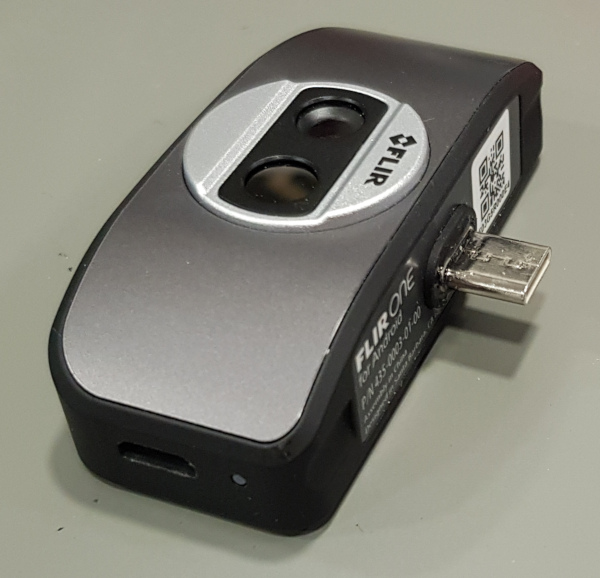
FLIR ONE is a nice product, with an extremely limiting battery and bad software. (Luckily, third-party software is much better)
You may say the battery has two reasons to be there: 1: Limit useful time: pushing users to a more expensive product. 2: Obsolescence by design: become useless as the battery age and stops working.
Goals: 1: remove the need for battery and charging. 2: replace the MicroUSB with USB-C
Special tools: You will need one security T5 (Torx5 with a hole in the middle)
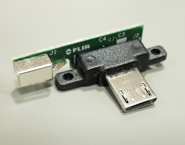
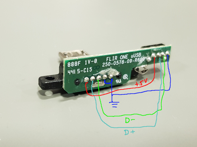
The original USB connector extracted from FLIR OneFast mapping of the connections between USB and mainboard.1: By heating the MicroUSB up, I removed it from the retainer. 2:USB-C OTG to MicroUSB adapter will be the donor for USB-C 3: This 4-pin motherboard connector will be re-used.
Using a Dremel multi-tool, I expanded the slot it the black connector retainer and the main body. Using adapter (2): after de-soldering its female MicroUSB – I glued the USB-C connector inside the black retainer using epoxy.
Please note: A reader of this article told me that I got the D+/D- swapped in this post. If what you do does not work: swap D+/D- (it’s harmless to swap them, but only the correct way will work)
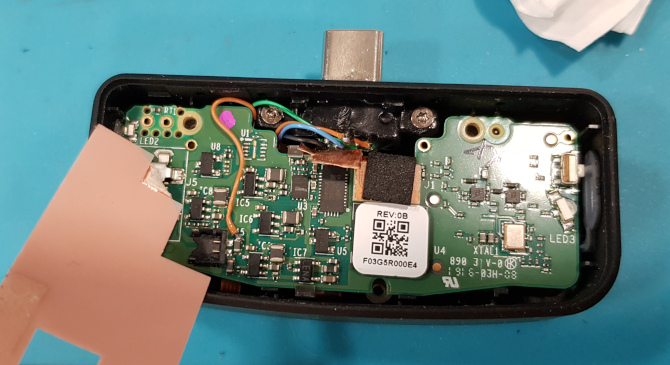
The new connector in place, wires soldered to the motherboard connector.Mainboard in place, observe the orange wire providing power where needed. No more battery.
Assemble, and throw away the battery.
USB-C in place.
There is no more need for charging or switching on the device. Also, it does not run out of juice after 5 minutes anymore 🙂
It’s working as expected. (The balancing connector header had 2mm pitch on PCB (my bad), therefore, this test version got a wire.)
All Calibration/setup/programming and firmware updates are done over the FTDI header.
Please do not think much about the poor flight time I got during early tests, the cells had a bit too high internal resistance and produced heat/dropped voltage too much. Better cells could be used.
11 January 2020:
Preliminary documentation for configuration over Serial port (serial port is used for configuration and firmware updates): Example commands in bold.
SC3256,3231,3255,3263 // calibrate cell voltage in millivolts for 4 cells. Users can also omit any cell to if one-by-one calibration is desired for some reason, like SC,,3300, – this may be useful if calibrating by a single, precise voltage standard source.
SI10220 //Calibrate current sensor in mA “SI10220” = 10.220A
GV //get firmware version SW //write valibration/linearization tables to flash
5 January 2020: designed some initial PCB’s – now with individual cell measuring and current sensing.
(I hope to start selling them as a product before March 2020)
15 December 2019:
Currently handled I2C requests (all that Solo is requesting:)
0x08 TEMPERATURE 0x10 FULL_CHARGE_CAPACITY 0x1C SERIAL_NUMBER 0x0F REMAINING CAPACITY 0x23 MANUFACTURER_DATA 0x28 CELL_VOLTAGE 0x2A CURRENT
This is an early version of a BMS for any 0-5v/cell chemistry 4-cell pack for ArduPilot.
Right now, it is more correct to call it an BMS emulator, than a BMS. A final product would measure individual voltages and the actual current. I started this way because it does not require a custom PCB and a minimum of discrete components.
This early version does handle all the communications, and makes the autopilot set the actual capacity (9Ah), reports voltage, and calculated individual cell voltages.
It does also calculate and report remaining capacity by doing a 15-point linearization and then interpolating a “voltage_to_capacity_table”. This method is good enough once one knows the battery characteristics and fly at about the same current later.
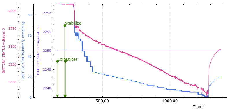
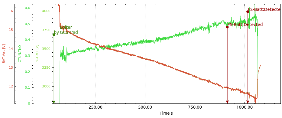
Test Flight1:
I did not wait for the 4S3P Li-Ion pack to charge fully. (Samsung 3Ah 18650-30Q cells) The outdoor temperature was about -5°C, batteries. Flight time was 17 minutes. With GoPro4Black + the brushless 3DR Gopro gimbal. The battery pack was 677gram. Included in that weight is 22gram that is the BMS microcontroller PCB, Solo battery connector and wires/connectors to battery.
The predicted SoC percentage (blue) is clearly not perfect (yet) it was good at the end, not at the beginning, but that is not a problem, as it is easy to change by modifying the table.
Notice that it can still climb at as low as 10.5v , not exceeding 70% of throttle.
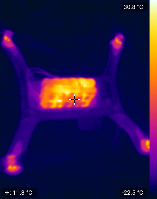
Post-flight thermal image: (somewhat affected by some kapton tape on the battery pack.)
TODO / Future:
Given enough interest, I plan to make a fully standalone BMS that can be user-customized to any chemistry, (min/max voltages) and so on. With balancing, real current sensing, fuel gauge etc.
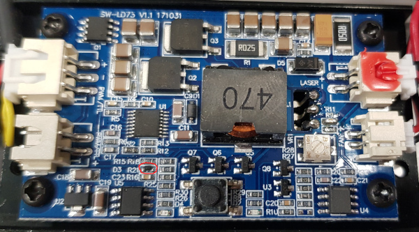
This laser driver board seems to be common for many <20W LED lasers used for cutting/engraving.
Whenever powered on, it defaults to full power due to a rather strong internal pull-up.
Most CNC machines have a laser TTL PWM output that goes into high-impedance mode on boot. In that case, any connection to, or reboot of the microcontroller will make the laser output full power for about 2 seconds while the user may not be prepared for that.
D3, in the red ring, provides power for the pullup.
.
The solution is to remove D3, which provides power to the pull-up, then the laser will not be “default on” anymore.
Update: As of Arducopter 4.0.0 for Solo, the motor slew rate is available, and this mod is NOT required if you are happy to use slew rate.( which gives a little less responsive copter, lust like the original 3DR fix.)
3DR Solo Cube (Pixhawk 2.0) outputs 3.3v PWM, the IO buffers run off 3.3v on both sides, while they are perfectly capable of delivering 5v. Using 5v is safer when using 3DR Solo firmware with PWM slew rate, and required for ArduCopter code on Solo.
The simple solution is to purchase “Green cube” (usually sold out) or modify Pixhawk 2.1
The alternative solution, is to modify Solo’s Pixhawk 2.0 Cube.
This does require some soldering skills, and can be done by any semi-decent repair shop if you cannot do it yourself.
(The width of the buffer chip is 4.5mm)
The two first images show two different PCB layouts of the Pixhawk 2.0 cube, so everybody should recognize, and stick to one 🙂
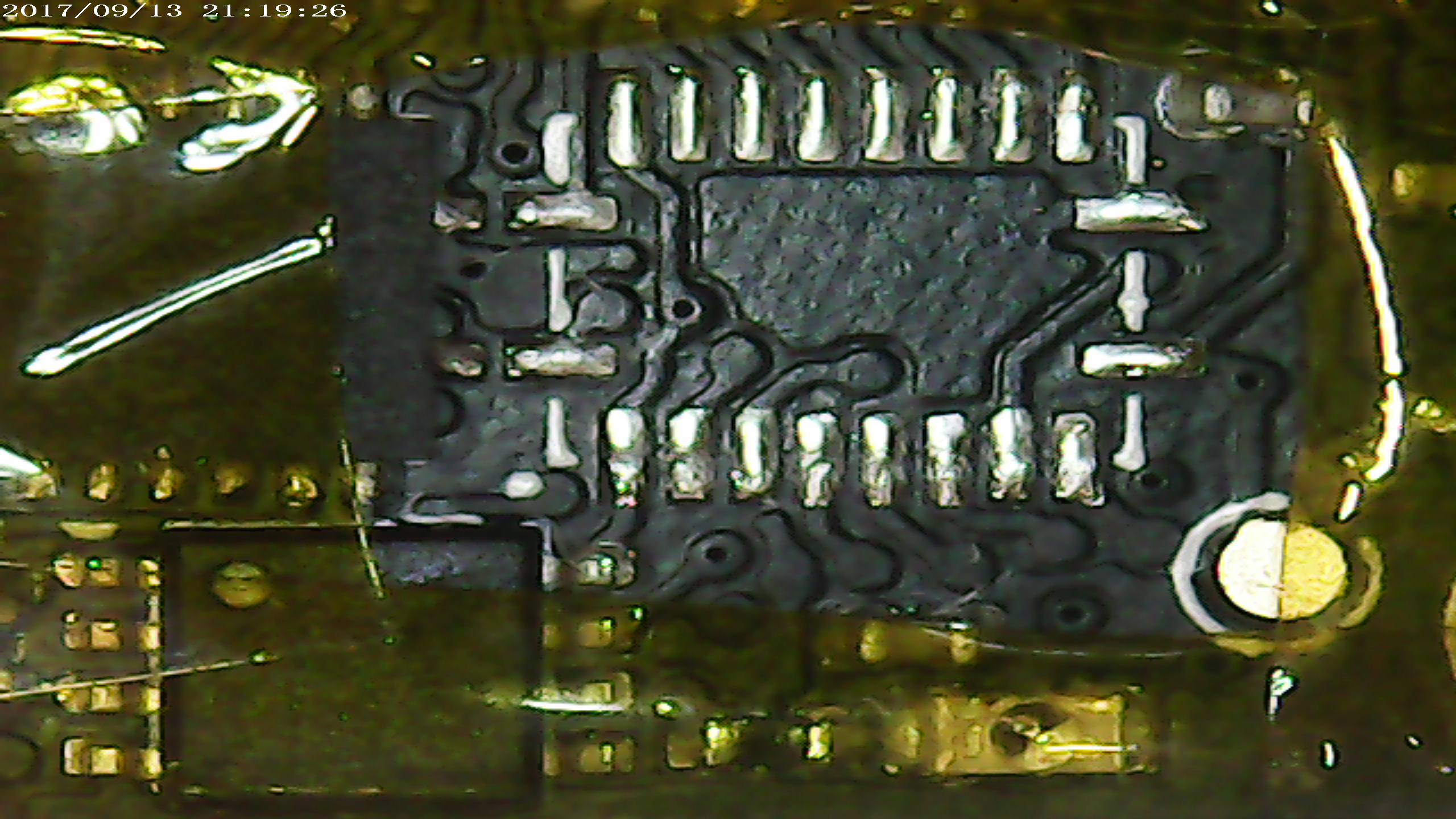
Open the cube, and locate the rightmost buffer ic. (TXS0108E marked YF08E)
Desolder the buffer (here seen on another PCB layout):
Cut the trace that feeds the upper left pad:
Re-solder the buffer:
Attach a thin wire to the pin. (provide 5v to the buffer’s VccB)
The other end of wires are routed to the clearly labelled 5v pad in the upper right corner of the Pixhawk2.0 :
Finally, clean and cover wire using conformal coating, to prevent vibrations to damage it: (UV inspection below)
Congratulations, output 1…8 output is now 5v.
Final note: the UV inspection picture picture shows another buffer, not used for PWM, the photos are taken on different occasions, and while batch processing many, not only one, so the time is not 30minutes between desolder and resoldering one device as timestamp may suggest.
Should you use a professional to do this job, it should take <15 minutes.
Modified files for uploading using Solex (Just copy into /Solex/download/package) – The only modification is to make Solex ignore the fact that the modified cube still runs the old 3DR fork of ArduCopter.
Once you upgrade to the 3.5.2 I provided here, you can continue to upgrade to newer versions using SSH /Solex and/or OpenSolo as if you had the greeen cube.
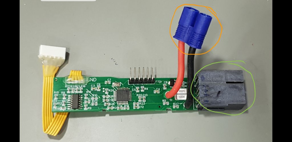
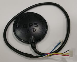
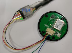
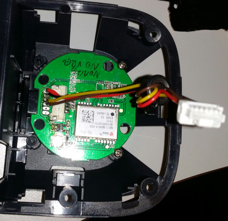
3DR Solo GPS upgrade to uBlox M8N – the cheap’n’simple ($15) way:
Be sure to buy a GPS that looks like this:
several sellers on Ebay sell them for less than US$15 including shipping from China.
4 Screws later, inside, strip the wire, and interface with a standard FTDI cable for configuration:
Using uBlox u-Center
Yes, it’s windows-only, that sucks, but it runs just fine in Wine , just make a link to the serial device like:
sudo ln -s /dev/ttyUSB0 ~/.wine/dosdevices/com5
configure NAV5 like this:
remember to store to flash:
Remove Solo’s GPS module, by making two small grooves in the pcb where the two screw-holes are, the PCB if held in place by the two original screws.
Cut off one of the connectors, and solder the wires to the pads:
Red=VCC
Black=GND
Yellow to TX
Brown to RX
Sony ILCE-QX1 has great specifications at low weight, which makes it good for UAV photogrammetry use. It can be configured using WiFi , then retain the configuration. (so it’s not necessary to even enable wifi for each operation.
About the modification:
The pop-up flash assembly is removed, an microcontroller replaces the flash assembly, it’s interfacing the motherboard indirectly, via FPC. The flash cover is slightly cut to make space for the servo (PWM input) and logic level output that indicates shutter operation.
Can reliably do manual-focus shoot every 700ms. (no drops)
The camera will continue to function normally as before when the PWM interface is not supplied with power, except for the flash.
The modification requires micro-soldering; most narrow are three points within 1mm distance. Naturally, it voids camera warranty. (so test camera well before getting it modified.)
Features of the modification:
Camera will not shut down when inactive..
3-wire servo connector (PWM input)
1-wire logic output (high on shutter) -allows precise GPS positioning of each photo, and confirmation to the AP that photo is taken.
Command “Shoot” (just trigger a photo, for preset/manual focus)
A quick demo, switching between 8 modes using a servo-tester. The TAU640 in this video is set for outdoor use, and does not show the full advantage of Ice&Fire modes inside.
What you get:
A microcontroller on a small PCB (18x33x3mm) with soldering pads. Preprogrammed with 8 different modes as in this video, or up to 10 custom modes (as ordered).
The circuit works on 5v, uses less than 10mA. You can connect it using 3 wires, just like a servo)
The modes are selected using a knob on your transmitter, PWM decide mode, just like a servo position.
Serial data, is sent from the device to your FLIR device using one wire – (assuming you have common ground)
The common modes in this test video shows 8 modes I’ve found very useful.
What you need:
FLIR TAU ,TAU2, or QUARK thermal core.
For TAU, “Wearsaver” helps a lot. – It offers big soldering pads for connecting to the Hirose 50p connector. RX(pin2)
For Quark , you need to connect the serial signal to pin 15 of the Samtec 60 pin – connector. or to the breakout board, if you that.
Connection instructions:
Connect PWM (white wire) from your receiver to pad9 on PWM>FLIR device
Connect “-” (black wire) from your receiver to GND on the PWM>FLIR device
Connect “+” (red wire) from your receiver to VCC on the PWM>FLIR device
Connect pad8 on the device to your RX pad on wear saver, thats solder pad with green ring in the picture below.
Connect ground and +5v to TAU (black and red pads in picture below)
Finally, for information only:composite video out is on the yellow pad, and video ground on the blue pad on the TAU wearsaver.
Default mode configuration is:
1, white hot, no zoom , spatial threshold gain 34d.
2 white hot, 2x zoom, spatial threshold gain 34d.
3 Black Hot, no zoom , spatial threshold gain 34d.
4 Black Hot, 2x zoom, Spatial threshold = 9d
5 Fusion,no zoom, spatial threshold gain 34d.
6 ICE & Fire, no zoom, spatial threshold gain 34d.
7 Rainbow, no zoom, Spatial threshold, Gain = 34d
8 ICE & Fire, no zoom , Spatial threshold 17d
You can output a PWM from an autopilot, controlled by GCS, having any GUI you prefer. – Or , if you are will be controlling the PWM directly from a RC radio, you do not need a rotary knob with steps, it’s perfectly easy to hit desired mode even with smooth knob due to the quick visual change, and equal “distance” between modes.
It’s long time since last time I published a new buildlog/project.
My new car needed a decent stereo, it had a “iProduct” interface, but I needed something better.
Unlike my previous car computer projects, I did not wish to install an amp + carputer in the trunk, and run VGA,USB and speaker cables forth and back. I wished to have everything integrated in the dashboard.
The idea was to build according to ISO standard, then use a Toyota<>ISO-harness adapter.
Using the ISO-Toyota harness and integrating an amplifier also makes it easy to control the car’s active sub kit and active antenna, without modification.
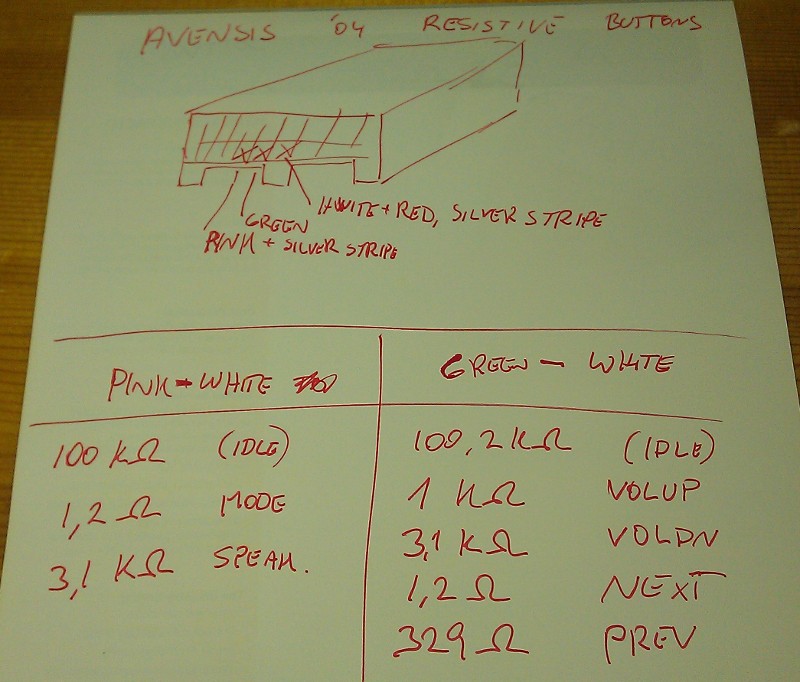
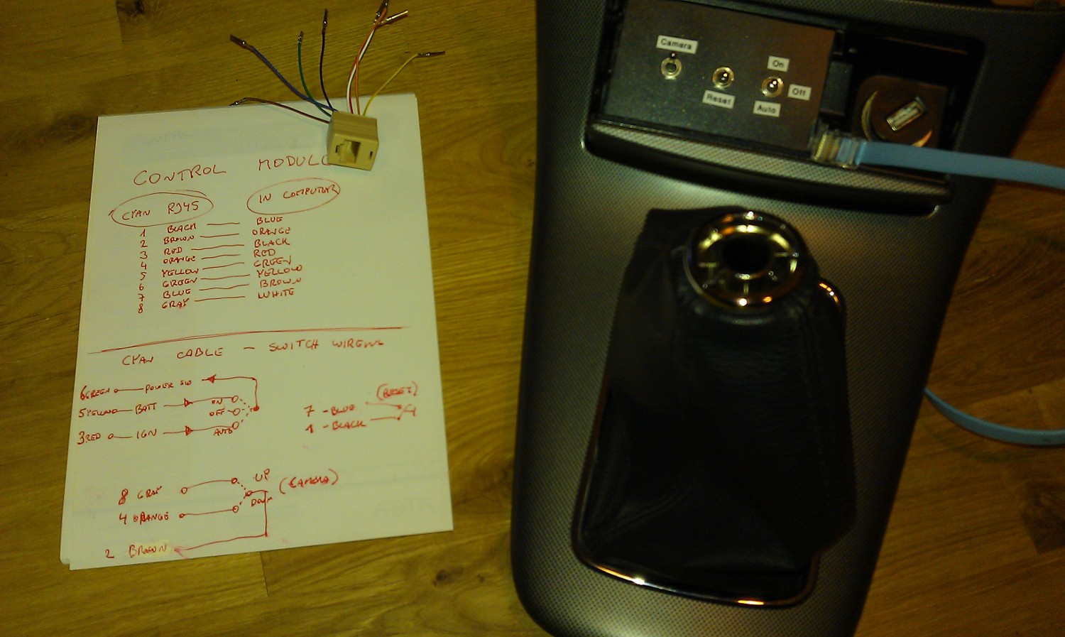
Analysis of the resistive buttons connector in Avensis
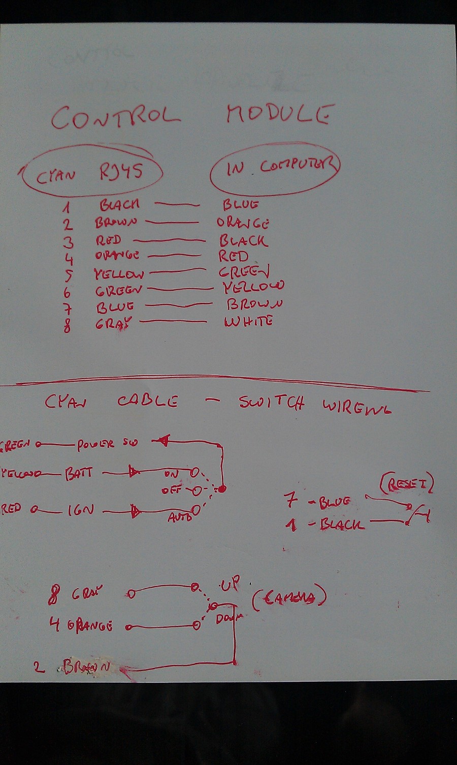
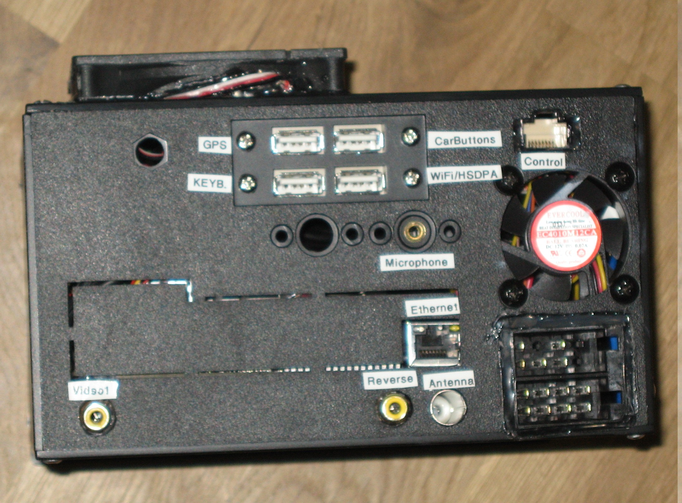
This is the control module interface documentation, a RJ45 connector between computer & external controls.
This is the control panel itself, controls power mode (always on/always off/follow ignition) camera select and reset switch built into the ashtray,(usually closed)
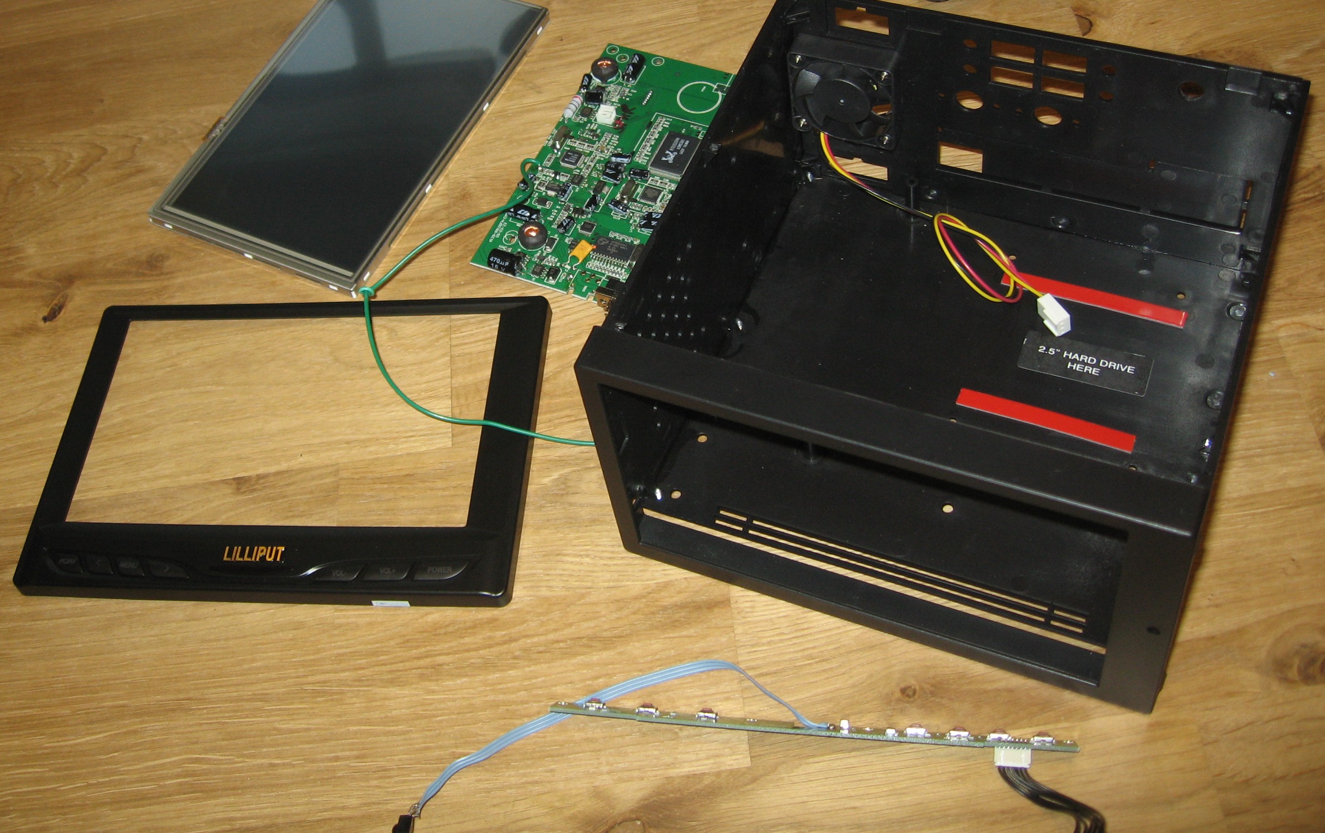
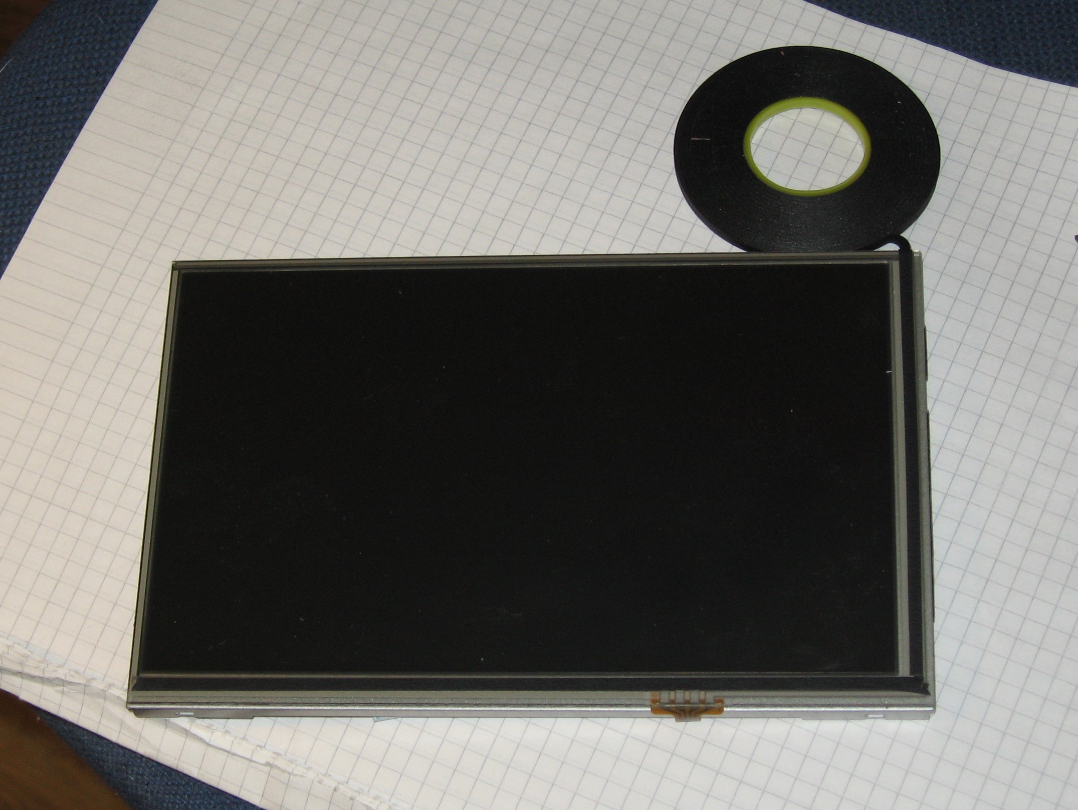
Lilliput 629 (7″ touchscreen) disassembled
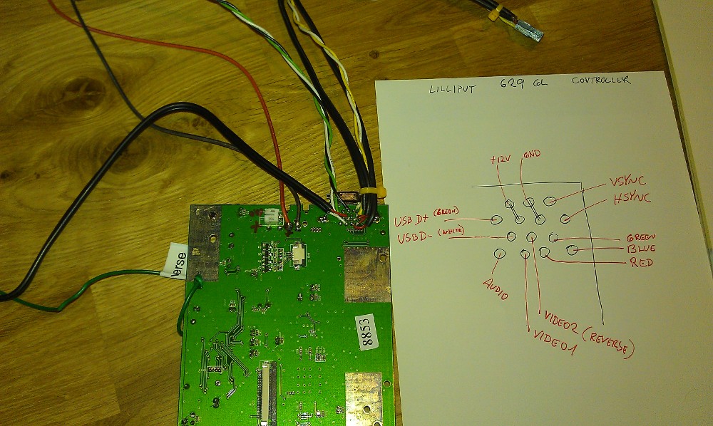
The resulting analysis of the proprietary connector of the display controller. Cables with proper motherboard connectors are now soldered directly to it.
The Lilliput needed to have some shielding cut off to fit better inside the (far from perfect) Double-DIN box
The display’s edges needed to be padded, to prevent the double-din frame from “touching” the touchscreen area.
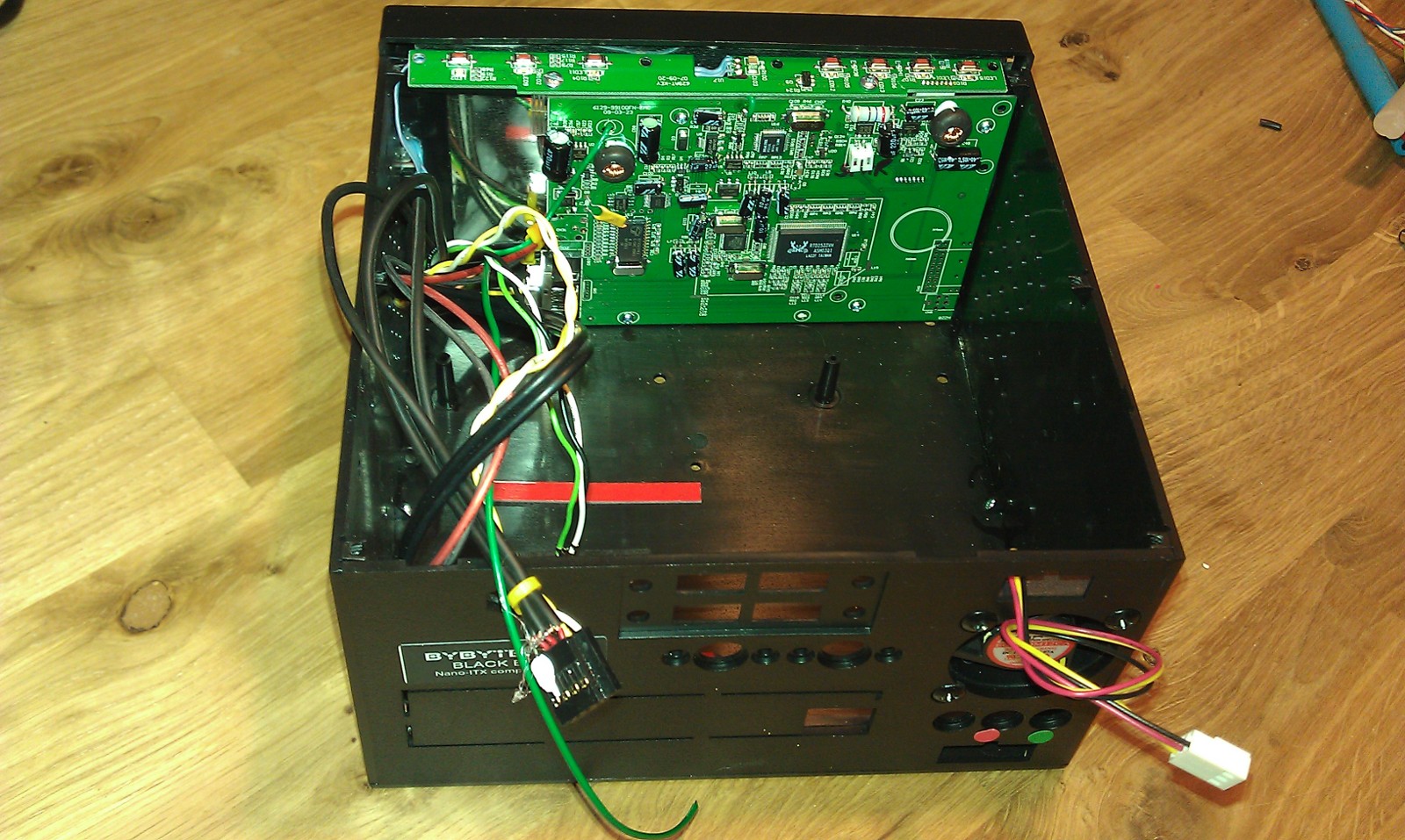
Display, and display controller installed, IR sensor and buttons relocated.
Don’t repeat my mistake, while waiting for this motherboard, I built proper 2,54 connectors for VGA,USB,Audio and so on, just to discover the pin headers on this motherboard are 2.0mm !
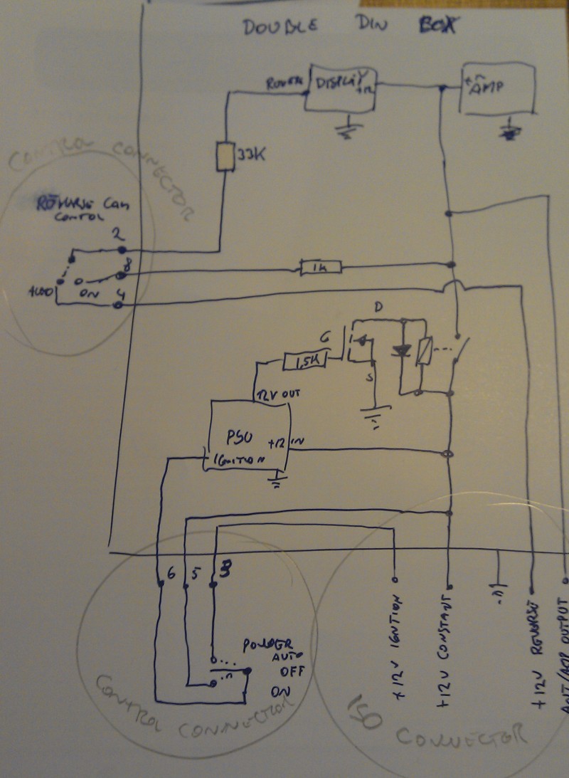
Circuit for relay control. (provides power to display, amp, external amp(active sub), and antenna output).
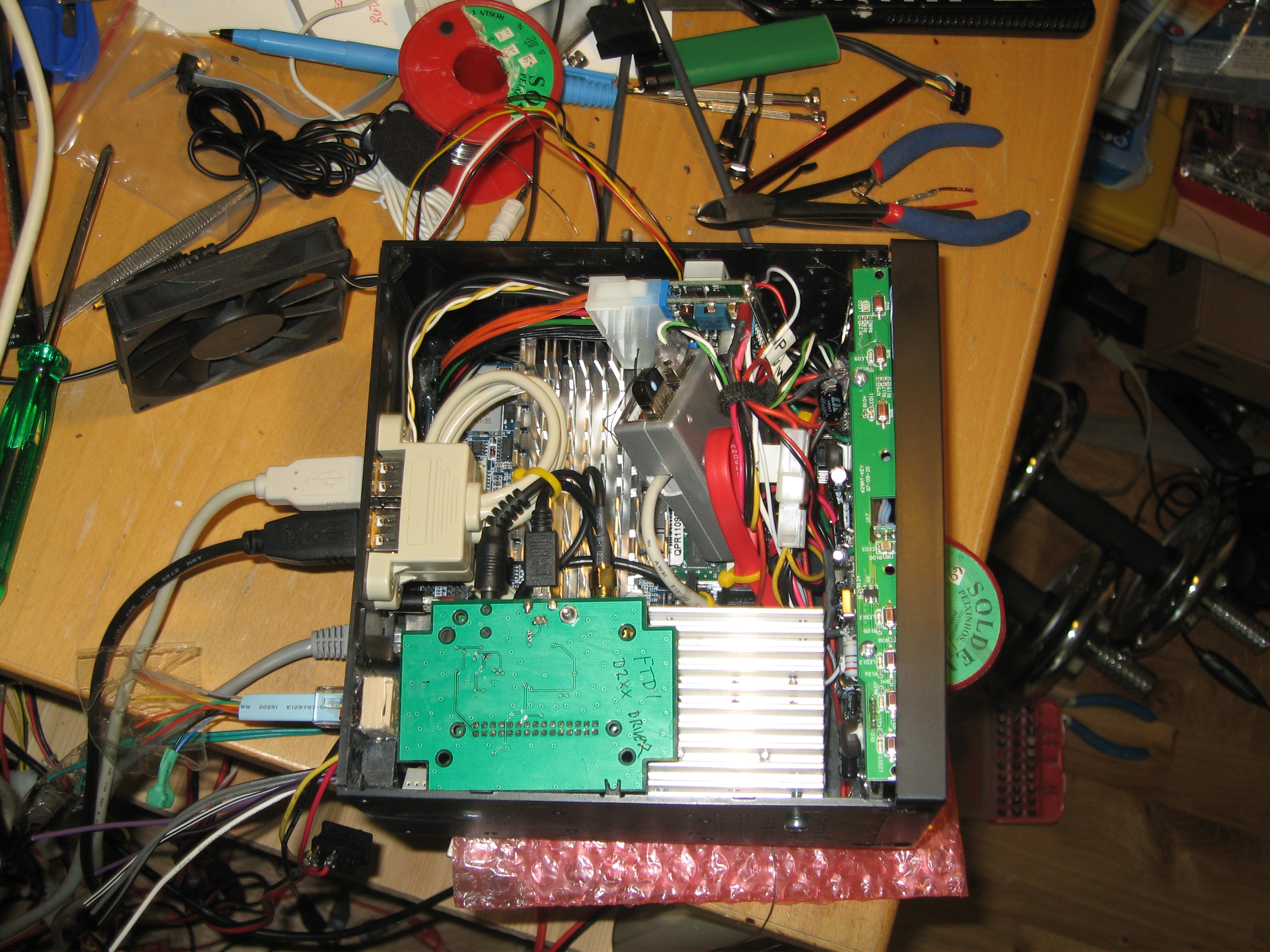
Motherboard+PSU installed, the hard-drive is below motherboard
The amplifier is now installed (built around a TDA7850 (4x~50W) plus BA3121 ground isolation amplifiers.).
Radio module installed, The blue cable in the control port simulates the “usual” control-panel configuration for lab-use (follow ignition) and use reverse camera
That’s it, ISO connector compatible device. with internal radio, and amplifier.
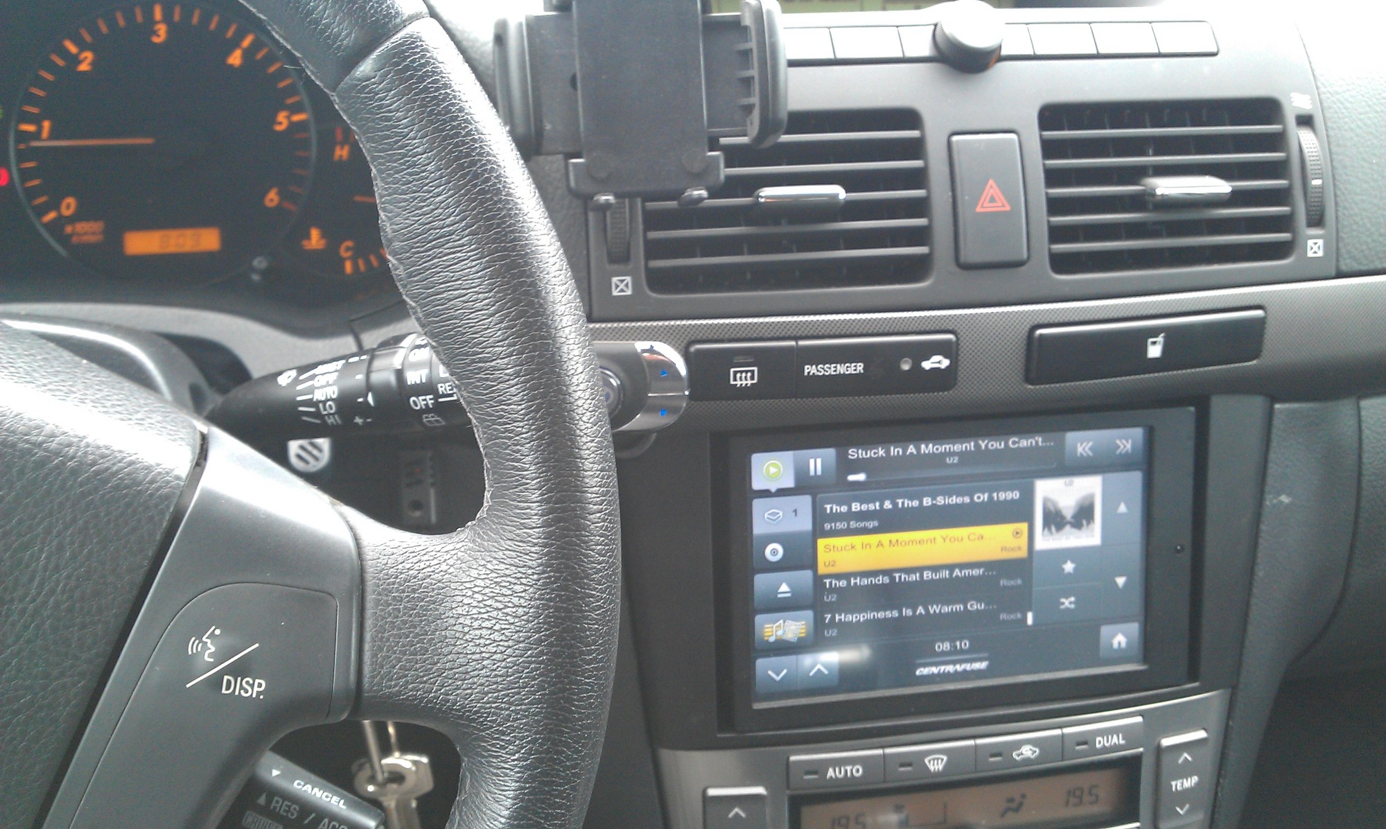
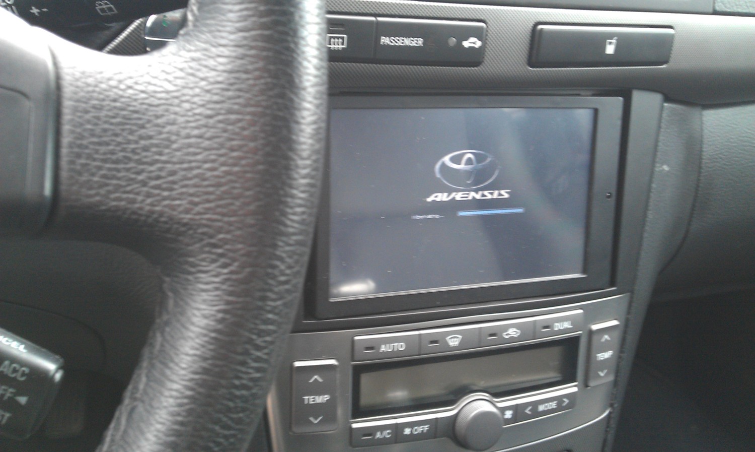
Installed in car, displaying reflection because it’s off.
Running Centrafuse
I also modified the “hibernating” screen with a custom logo – removing windows logo feels good, looking forward to the release of Centrafuse for Linux.