Interface Overview
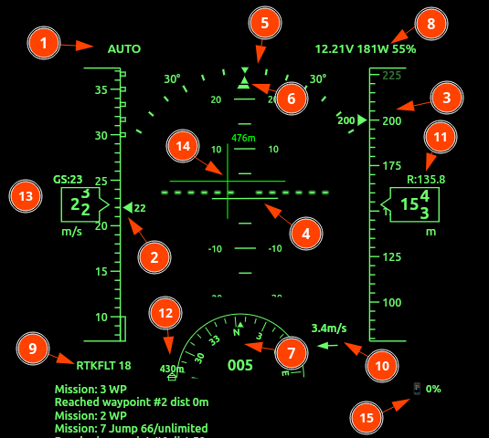
- Flight Mode & Status: Located top-left. Displays current state (e.g.,
AUTO). Displays also the state of Safety or Arming. - Speed Tape: Shows Indicated Airspeed (IAS). Long boxed areas represent stall speeds; checkered areas indicate overspeed limits. Units are selectable.
- Altitude Tape: Displays current altitude. Units can be m/s or feet.
- Artificial Horizon (AHI): Central attitude indicator. Features a pitch ladder (horizontal lines) and a fixed aircraft symbol to show relative pitch and roll.
- Bank / Roll Scale: Displays the current roll angle. The moving triangle (pointer) indicates degrees of bank.
- Slip/Skid Indicator: Small bar below the bank pointer.
- Heading Indicator: A compass rose showing degrees (e.g.,
165). - Battery & Power Status: Top-right. Shows Voltage (
V), Power (W), and Throttle percentage. Blinks during low-voltage, faster during critical voltage. - GPS / RTK Status: Bottom-left. Displays fix type (e.g.,
RTKFLT) and satellite count (e.g.,18), flashes in case of GNSS loss. - Wind Indicator: Shows wind speed and an arrow representing direction relative to the current heading.
- Rangefinder Altitude: Displays precise distance to ground if a Radar,LiDAR or sonar sensor is active.
- Home Indicator: Indicates distance and bearing back to the launch/home point.
Detailed Feature Descriptions
1. Speed & Altitude Tapes
The tapes are dynamic vertical scales.
- 13: Ground Speed (GS): Displayed numerically above the speed tape.
- Target Bugs: Visual markers on the tape indicate set cruise speeds or target altitudes.
2. Navigation Display (Active Flight Plan)
When a navigation is active, the following elements appear:
- 14: Flight Director (FD): Crosshair or bar symbols on the AHI guiding the pilot to the target path.
- Waypoint Info: Bearing and distance to the next waypoint are displayed as overlays.
3. Connection & Safety Alerts
- MAVLink Status: If the data link is interrupted, a prominent “MAVLink lost” warning appears in the lower right with a disconnection timer.
- App Status: Similar warning for the mobile/tablet application connection.
4. Hardware Monitoring
- 15: Device Battery: The UI includes icons for the battery level of both the Rokid Glasses and the connected telemetry phone/tablet.
- Status Log: The bottom area (not shown in snippet) scrolls
STATUSTEXTmessages from the Flight Controller, providing real-time diagnostic feedback.
Alerts and Notifications
The system provides both audible and visual alerts. The list below describes each alert, what triggers it, and whether it applies to copters, planes, or both.
Audible alerts
Stall alert
A repeating stall warning sounds when indicated airspeed drops below the configured stall-speed threshold. This alert is only active when the aircraft is armed, receiving MAVLink data, and in the air. On VTOL aircraft, it is only used in fixed-wing flight states.
Applies to: Planes only
Overspeed alert
A repeating overspeed warning sounds when airspeed rises above the configured overspeed threshold. The current implementation does not limit this by vehicle type.
Applies to: Copters and planes
Bank-angle alert
A repeating bank-angle warning sounds when aircraft roll exceeds the configured bank-angle threshold. It is only used for aircraft identified as planes, and only while airborne. It is suppressed if stall or overspeed alerting is already active.
Applies to: Planes only
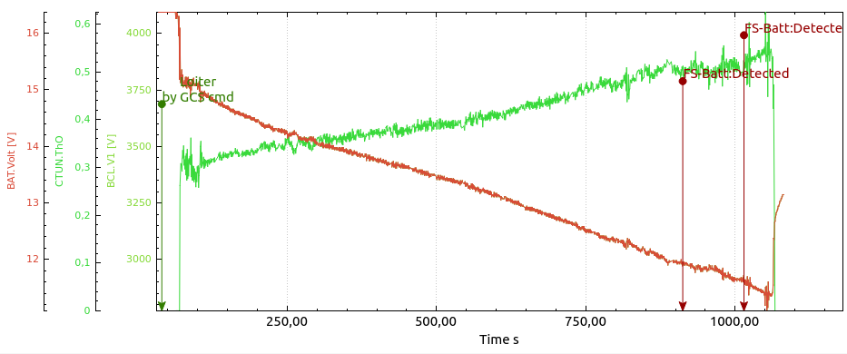
Battery low
A spoken “Battery low” warning is issued after battery voltage has remained below the low-voltage threshold for 4 seconds. It repeats every 30 seconds while the condition continues.
Applies to: Copters and planes
Battery critical
A spoken “Battery critical” warning is issued after battery voltage has remained at or below the critical-voltage threshold for 4 seconds. It repeats every 30 seconds while the condition continues.
Applies to: Copters and planes
GNSS lost / GNSS fix restored
A spoken warning is issued when GPS quality drops below a 3D fix, and another spoken notification is issued when 3D-or-better fix returns.
Applies to: Copters and planes
MAVLink lost / MAVLink restored
A spoken warning is issued if MAVLink telemetry stops arriving for about 2 seconds, and another spoken notification is issued when telemetry returns.
Applies to: Copters and planes
App connection lost / App connection restored
A spoken warning is issued if the HUD/PFD app stops acknowledging forwarded packets for about 2 seconds, and another spoken notification is issued when the connection returns.
Applies to: Copters and planes
Arming / Disarmed
The system speaks when the aircraft arms and when it disarms. On disarm, it also speaks the total armed time.
Applies to: Copters and planes
Safety on / Safety off
The system speaks when the safety-switch state changes.
Applies to: Copters and planes
Flight mode change
The system speaks the new flight mode whenever the reported autopilot mode changes.
Applies to: Copters and planes
Speed callouts
The system can speak rounded speed values while below a configured speed threshold. In MAVLink mode, this only happens while the aircraft is armed and in the air.
Applies to: Copters and planes
Altitude callouts
The system can speak rounded altitude values while below a configured altitude threshold. The altitude source may be relative altitude, rangefinder altitude, or absolute altitude depending on configuration. In MAVLink mode, this only happens while the aircraft is armed and in the air.
Applies to: Copters and planes
Demo or trial reminder
In trial mode, the system periodically speaks a reminder message while armed.
Applies to: Copters and planes
Visual alerts and notifications on the HUD
Battery caution
The top-right battery, power, and throttle field slow-blinks when battery voltage is below the configured low-voltage threshold.
Applies to: Copters and planes
Battery critical
The same top-right field fast-blinks when battery voltage is at or below the configured critical-voltage threshold.
Applies to: Copters and planes
GNSS caution
The lower-left GPS status field slow-blinks when fix quality is below 3D.
Applies to: Copters and planes
Flight mode, safe, and disarmed indication
The top-left field shows the current flight mode. When the aircraft is disarmed, the label is prefixed with SAFE: or DISARMED:.
Applies to: Copters and planes
Status-text messages
Incoming MAVLink STATUSTEXT messages are displayed in the long status-text area and retained in recent history.
Applies to: Copters and planes
Demo or trial banner
In trial mode, a reminder message is shown in the long status-text area and added to history.
Applies to: Copters and planes
Test-data indicator
When manual test data is being used instead of live MAVLink telemetry, the top-right field shows TEST DATA with a slow blink.
Applies to: Copters and planes
Android system notification
MAVLink Relay Active
On Android, the app may show a persistent foreground-service notification labeled MAVLink Relay Active while background MAVLink relay is running. This is a system-status notification, not a flight alert.
Applies to: Copters and planes
Notes
Stall alerting is intentionally plane-only. Overspeed alerting is currently not vehicle-filtered, so it can trigger on either copters or planes if enabled and the configured threshold is exceeded.
The HUD also supports visual emphasis codes in incoming text fields: solid invert, slow blink, and fast blink. These are used internally for attention-grabbing status and caution displays.