How to connect more temperature sensors to Motherboard Monitor
Motherboard Monitor by Alexander van Kaam is a great freeware that uses hardware monitoring chips found on many Pentium and all newer motherboards. MBM will automatically detect and use the circuit described below.
Some motherboards have 3 external temperature sensors ,other have 3 internal.
Some can monitor negative voltages , other does not. They all have one thing in common : the SMBus.
Want to add 5 , 10 or 45 more temperature sensors ?
I am using water cooling and “needed” more than my 3 temperature sensors (as one is on motherboard and the two others monitors the two CPUs) , after looking into the wide sensor support MBM offers I decided to try to attach another chip to the SMBus (Intel’s version of Philips’s I2C multimaster bus).
MAX1668 16 pin QSOP IC. (datasheet)
You can get one at http://www.maxim-ic.com/
The 1668 offers one local (on chip) sensor and 4 diode-coupled-transistor sensors.
Transistor-sensors is what you want , a little more work , but more accurate , and they already exists in CPU’s , GPU’s and other IC’s with internal sensor.
The schematic is very easy , and needs few external components. 
(*)= 2200pF capacitors –not needed if you use twisted pair wires.
(*)= +.1uF capacitor – used for decoupling.
(*)= 200Ohm resistor – can be omitted (just use a wire instead) as you use only 5volt (SMBus)
(*)= 10K resistor –not needed, as you are not using ALERT output.
The sensors , (transistors) can be BC547 with basis connected to collector. they work only when connected correctly , there is no risk to damage anything if reverse-connected, the sensor will not work until corrected..
BC547 is a very old , cheap , and small transistor , and it’s body volume can be reduced to less than half with a Dremel-tool. (the copper/silicone part is really small) There is no need to use any expensive transistors , all that really matters is that it’s a silicone (not germanium) transistor , and not a darlington coupled one.
Addressing:
Each MAX1668 have an 7 bit address that is unique to this SMBUS device, and no other similar device will have. The 3 LSB (least significant bits) of this adress can be changed by ADD0 and ADD1 pins.
If you want to have more than one MAX1668 on the SMBUS, each of them needs and unique address.
The table below shows the 9 possible configurations, and where to connect ADD0 and ADD1 pins:
| ADD0 | ADD1 |
| GND | GND |
| GND | Floating |
| GND | VCC |
| Floating | GND |
| Floating | Floating |
| Floating | VCC |
| VCC | GND |
| VCC | Floating |
| VCC | VCC |
(Floating means “not connected”)
…YES , It means you can have nine MAX1668 on the same SMBus at the same time with no problems , just make sure each have it’s own unique address. Just choose an address , MBM will detect any.
Any unused sensor inputs should be shorted (to prevent floating) , and shorting one tells the chip that sensor is not in use.
SMBus Connector:
Motherboards SMBus connector is 5-pin and is configured like this:
1-CLOCK
2-(not used)
3-GND
4-DATA
5-+5Volt
Most decent motherboards have such connector, if you cannot find it, or your motherboard do not have it, thengo to my “locating SMBUS” page for instructions.
The challenge….
…Is to connect the small QSOP package MAX1668 comes in.
You should be happy MAX1668 is so small , with that little body it picks up temperature changes really quick (local sensor in huge packages is always sluggish)
So all you have to do , is connect those pins , each pin is 0.25mm wide, and there is one pin each 0.6 mm.
That is : “on less than 5mm there is 8 pins to solder”.
SMBus uses only weak (20mA) open collector outputs. Theoretically it’s impossible to destroy I2C or SMBus by short Data and/or Clock to GND or VCC or to each other.
The easy way….
You can order a prototype QSOP PCB http://smt-adapter.com/ (*) that have large terminals and are easy to work with .. or you might look for it at www.elfa.se , if you get such pcb , then just place the QSOP package on the PCB and heat up the terminals , no soldering needed.
*Thanks goes to Brian Macomber for providing the link.
Some Pictures….
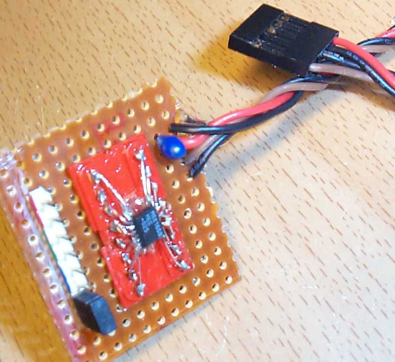
…This is how mine MAX1668 board looks , the chip is mounted on a DIL16 socket, the 8 pins to the left are 4 connectors for external sensors (you can see they are color-coded) , the last one has a jumper , a jumper instead of a sensor tells the chip that this input is not used , and it returns 0°C.
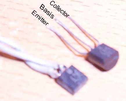
This is one of the “sensors” , a modified BC547 transistor , as you see it’s less than half size of a normal BC547 , I’ve made even smaller ones now. The transistors should be “diode-coupled” – it means their basis and collector is shorted. One wire goes to the basis+collector , the other to emitter.
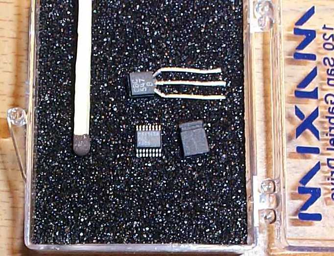
This picture shows the size of MAX1668 compared to some known objects , (BC547 transistor and a jumper)
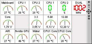
“Air” – is the local on-chip sensor
“Nvidia GPU” is a transistor-sensor on the back side of PCB where the GPU is.
“Water” is usually water temperature , , showing maximum temp , because it’s disconnected to demonstrate what you see before sensor is correctly connected
Thanks to:
-Antonio , for reporting an error on this page , and helping with a fix.
-Chris, for grammar check.
-Lee Hollis – for showing people how he accomplished this project
-Andreas Lenz – for showing people how he did it, in German
