This product is discontinued.
Version2 is here: https://madhacker.org/bmsone-2-universal-2s-6s-bms-for-ardupilot/
This BMS is very flexible and universal, you can fly any 4-cell battery chemistry/capacity that the Solo can handle in terms of voltage & weight, anything that produces 10-20v(I did not actually research/test Solo’s upper voltage limit)
The PCB is less than 50x40x9mm (the balancing connector is the highest component) The weight is only 7.6g
There are three mounting holes that should enable nice mounting inside the GPS bay (I did not test it, just measured it.)
It is very user-friendly, and requires very little prior knowledge about computers/serial communication to follow.
20 January 2020: Firmware 1.4
Verified support for Solo 1.3.1…1.5.4 – this firmware corrects a minor typo in 1.3 that prevented it from working on Solo 1.x.x as advertised thanks to the people behind a much more PnP version: https://jonbrotherton.fws.store/BMSOne_Plug_and_Play/p5973142_21044679.aspx
23 September 2020: Firmware 1.3-test.
This is not a release, because it does not do anything new for OpenSolo users, it does, however, respond to messages Solo 1.3.1…1.5.4 request – so if anyone flying those versions can confirm that it works – it will become a release.
There are no other changes in features/adverse side effects, only this additional code.
Another Bonus of that is that the Solo Battery tool can read the main voltage properly. 🙂
13 June 2020: Firmware 1.2 released. Thermistor was added for monitoring of battery temperature. All new devices are delivered with a thermistor.
All boards ver1.2 (with “Temp” input) can use a 100k NTC thermistor.
All boards ver1.1 devices can be modified with an NTC between GND and pin22 of the microcontroller, and a pullup resistor of 100k with a pullup to +5v.
I have also added some LED blinking.
16 Mai 2020: The first FIRMWARE UPDATE is out! (1.1) And I have published a configuration for Tattu 5200mAh battery (see below) – from now on, this will be the default configuration, as I have the impression that more people fly with Li-Po than Li-Ion.
Important information: (for devices shipped before 16 Mai 2020):The BMSOne comes configured for Li-Ion cells, (down to 2.5v/cell – check the datasheet.) – watch the cell/voltage pack reading unless you are sure you did configure it properly for Li-Po
Operation modes:
The device can provide remaining capacity information based on one of the methods:
S0 : remaining capacity is estimated based on voltage.
S1 : actual capacity reported based on mAh consumed (assumes you start with a fully charged battery of defined capacity on boot)
Firmware upgrades:
It can be fully configured using an FTDI cable (or any USB<>Serial cable with RX,TX and DTR signal- DTR is only used to enter the bootloader, and only useful for flashing, although it is possible to flash it without DTR too)
All firmware versions apply to all BMSOne hardware versions unless stated otherwise.
To flash the new firmware you will need the avrdude application.
On Linux, it’s installed by: “sudo apt install avrdude”
The firmware upload command is:
avrdude -patmega328p -carduino -P /dev/ttyUSB0 -b115200 -D -Uflash:w:BMSOne.1.1.hex :i
Windows users need drivers for the serial<>USB cable, avrdude application: http://download.savannah.gnu.org/releases/avrdude/avrdude-6.3-mingw32.zip and the firmware (download link below). Extract both firmware and avrdude to the same directory.
Then replace the “/dev/ttyUSB0” in the example command with the “COMx” name of your serial port, and execute the command.
Please note that the programming protocol is Arduino compatible just enough to make it work with avrdude, but it’s not fully Arduino compatible as a bootloader, (and much smaller).
Firmware 1.1: Perfectly nice interpolation and smooting.

Firmware 1.1 also has some cosmetic changes in the terminal and comes with the Tattu 5200mAh 35C linearization curve as standard.
It will NOT overwrite your existing configuration. To apply Tattu /Li-Po defaults, look up Tattu further down on this article.
CAUTION: The bootloader is well tested, it handles interruptions in upgrades and can upgrade/downgrade firmware regardless existing of version. You should NOT attempt to use “avrdude”, “winavr” or “avrdudess”, or any other tool/command except those described above. The only known case of messed up bootloader reported to me for BMSOne or SoloBatt tool, was caused by experimenting with such tools.
Firmware 1.2 : Battery pack temperature sensor:
Firmware 1.3-test – should work with Old Solo v1.3.1…1.5.4
Firmware 1.4 – Works with the old Solo v1.x.x
/
Super-Simple solution:
If you dislike configuration, finding a suitable battery etc.. please see the super-user-friendly version made by some nice people at: https://jonbrotherton.fws.store/JBBMSOne_Liion_Edition/p5973142_20662335.aspx
Basically: It gives you a simple plug-and-play solution, none of the setup/configure/install/mount stuff.
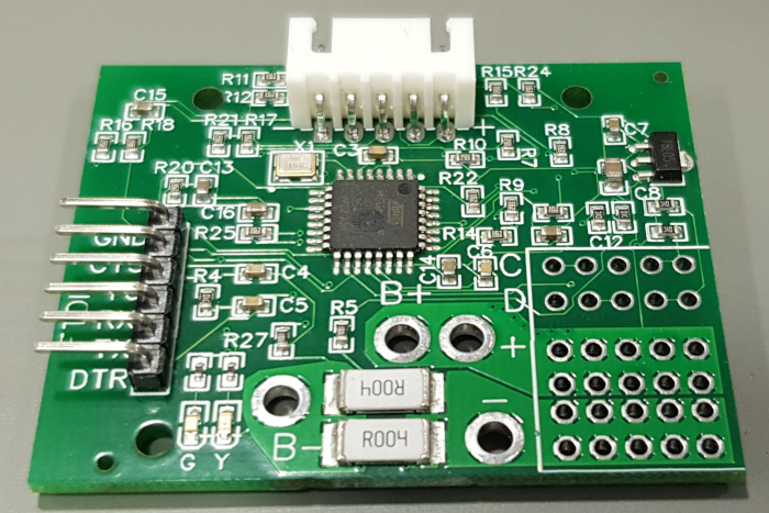
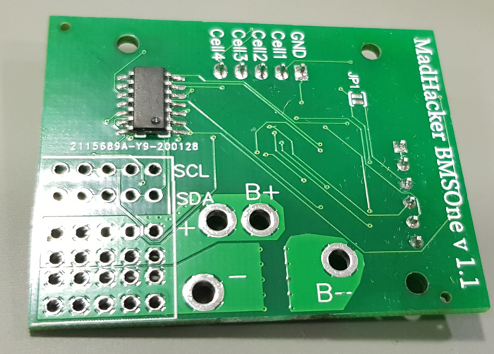
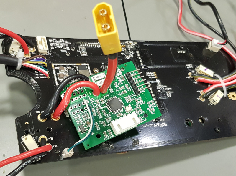
This is the BMSOne:
BMSOne+XT60 connector
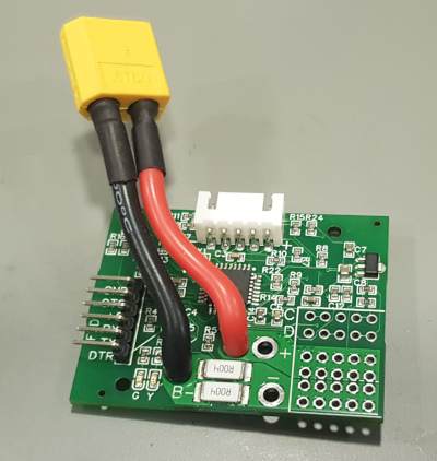
You can extract the gray power connector from a dead battery: Instructions here: https://madhacker.org/simple-desoldering-of-the-solo-battery-connector/
Plug’n’Play:
A few people asked whatever BMSOne is “plug’n’play”.
Yes, it is kind of that, the simplest job is done right out of the box, once you connect a battery thru it, you will see the battery, and cell voltage, which is the most important information.
To have a nice, linear, SoC based on voltage or current used, some configuration may be required, there is no “one setup fits all” configuration. (but the default is pretty much food for most Li-Po’s) This is the price of having one BMS, many batteries, vs having a dedicated BMS for each pack.
As you no longer have the shutdown signal from the battery, the GoPro will remain on after pulling the battery, so you need to switch it off manually.
Power for programming/configuration:
Hardware version 1.3 uses a diode, and the device can be connected to FTDI regardless of battery being connected or not. For calibration, +5V from FTDI should be disconnected.
Hardware version <1.3 have a solder-jumper “JP1” on the solder-side of the PCB.
If JP1 is open, just connect FTDI , and provide power from a battery (FTDI’s +5v is disconnected)
If you wish to do programming/configuration without a battery connected, solder a blob over JP1 then connect FTDI cable with +5v – it will power the device. – do not apply battery powered from FTDI.
Configuration:
Configuration, like firmware updates, is done over FTDI-adapter.
For configuration, any USB-Serial adapter will do.
You could use the typical 6-pin FTDI adapter, but you can also just connect a 3-wire adapter, using GND,RX,TX, while powering the device from a battery.
When you connect to it at 115200kbps, (8N1) and power it up, you will see: BMSOne v1.1
Set the capacity of the battery in mAh using the command:
SM10000
it will respond:Set capacity: 10000
Now, you have defined a 10Ah full capacity.
You can type:
S0 //Select voltage-based SoC (State Of Charge)
S1 //Select capacity-based SoC
S! // No thermistor, fake 22.5°C temperature
SH //100K Thermistor
SW //write configuration to flash – until you do this, all your changes/calibration are temporary and can be reverted by rebooting the device.
SR //read config from flash (it happens on every boot)
SS //Show config
Displaying Configuration:
 Voltage table: 104, 110, 113, 116, 119, 122, 126, 129, 132, 135, 138, 142, 145, 148, 168,
 Capacity table: 0, 4, 12, 20, 29, 37, 45, 53, 62, 70, 78, 86, 95, 99, 100,
 SoC by Voltage
 Cell voltages(mV):3727,3731,3739,3744
 Pack voltage(mV):14941
 Current (mA):-152
 Full capacity: (mAh)10000
 Remaining capacity by Voltage: (mAh)9900
 Remaining capacity by Current: (mAh)10000
SD //Show internal data
You can also perform AD calibration.
When calibrating voltages/current sensor, it is important NOT to provide power from the FTDI connector. (otherwise, the precision will suffer.)
On the solder side of the PCB, there is a solder jumper “JP1” – to ensure a correct calibration, you can remove its solder blob – OR, simply disconnect the +5v pin from the FTDI connector.
With a battery hooked up, you can measure its cells, then provide a command like this: the numbers are voltages in millivolts.
let’s say you measured 3.256v, 3.231v , 3.255v and 3.263v then enter:
SC3256,3231,3255,3263 // calibrate cell voltage in millivolts for 4 cells.
If you can’t measure with 3 digits, – let’s say you can measure with lower precision “3.21v” then enter “3210”
SI10220 //Calibrate current sensor, value in mA “SI10220” = 10.220A
Again issue the command with a known current flowing through the device. It is better to calibrate while sensing 10A than 100mA.
Capacity by voltage linearization table:
For Li-ION:
SV10.4, 11.0, 11.3, 11.6, 11.9, 12.2, 12.6, 12.9, 13.2, 13.5, 13.8, 14.2, 14.5, 14.8, 16.8 //set 15-point percent linearization table
SP0, 4, 12, 20, 29, 37, 45, 53, 62, 70, 78, 86, 95, 99, 100 //sets 15-point percent table.
So by the example above 11.3v (third value) equals to 12% , (while 11.5v will be interpolated to a little less than 20%.
For Tattu 4S1P 5200mAh 35C
Thanks to Gary Pang’s generous donation of such battery, here is a configuration for this battery:
S0
SV14.0, 14.1, 14.2, 14.3, 14.4, 14.5, 14.7, 14.8, 14.9, 15.0, 15.2, 15.3, 15.8, 16.0, 16.8
SP0, 8, 21, 27, 41, 49, 57, 64, 72, 80, 85, 88, 98, 99, 100
SM5200
SW
ArduCopter 4.x battery safety settings:
These settings are for ArduCopter 4.x , which you should be using with OpenSolo 4.0 or newer. The BMSOne does work with OpenSolo 3 and AC3.6.x too, but it does not work with the original, old , forked 1.5.x versions of the autopilot, (nor should you fly the old versions)
If you use S0 mode(default), set low and critical-voltage thresholds:
BATT_LOW_VOLT
BATT_CRT_VOLT
If you use S1 mode(capacity based), also set low and critical-capacity thresholds:
BATT_LOW_MAH
BATT_CRT_MAH
Finally, these parameters define what action is taken:
BATT_FS_LOW_ACT
BATT_FS_CRT_ACT
SoC Voltage mode explained:
S0 = State-of-Charge by Voltage
This mode is beautifully simple and reliable, as you can use any number of battery packs, with same type of cells, and have perfectly fine SoC estimation (see battery percentage drop)
Advantage of this mode is that it works by voltage under load, so you can have one BMSOne and any number of packs, and any state of charge on those, and still, it will “just work”
We all remember how fast the remaining capacity drops on a Solo battery at the end, 20% can fall to 3% within one minute.
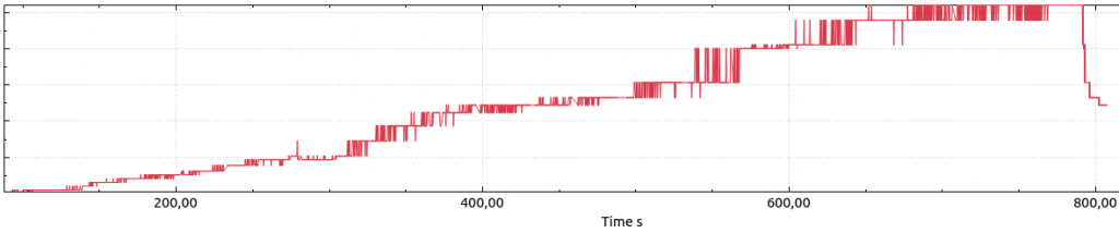
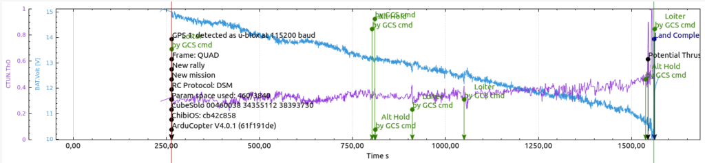
The first graph is made using these packs’ first flight.
It estimates energy as consumed a bit fast in the beginning, then just a little faster after 19/20 minutes.
Then the voltage/capacity table is corrected.. and watch the second graph, beautiful linear estimation, no surprises there even as the battery gets to 2.5v/cell.

Another aspect of SoC by voltage, is that it is most accurate when at normal cruise/hover. During a fast climb, the voltage will drop, and while climbing, you will see a lower estimate, and during a fast descend, you will see a higher estimate.
21minute flight example:
(I flew in bad wind conditions, now I see that the flight had the 4.0.3 PID issue that surely affected the flight time in a bad way)
4S3P Samsung INR18650-30Q (12 cells) 620grams with BMSOne.
GoPro Gimbal with Gopro 4 Black. AUW 1950g
Cells bought from Banggood (please observe that this is not a referral link, I get no kickback, nor can I guarantee the authenticity of a later batch).
I landed at 2.6v/cell, yet the manufacturer’s datasheet use 2.5v as the cutoff.
How to make a linearization table:
Let’s say you have a battery with given chemistry that you want to charge to 16.8v max and fly down to 14.0v minimum voltage. None of the known tables work well for it.
On a day with calm or no wind, fly slowly or hover well out of ground effect.
Monitor voltage of the individual cells and fly the pack down to the desired 0% state, for example, 14v.
The most important part is not to affect the discharge curve by hard flying or rapid climbs/descends. You want to see the pack’s normal voltage drop under normal load.
Get the log from the Solo, and plot BAT.Volt using APMPlanner2 or similar tools.
Now imagine, or draw some number of data points you want to read out, they can be spaced out by time on x axis, or , better, you can increase density where the voltage is less linear like illustrated with red lines below:
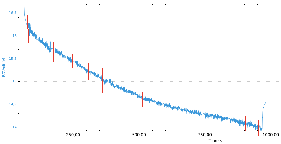
Your first data-point would be full pack voltage 16.8v, 100%
The next one, the voltage that is measured right after takeoff, you can see voltage drop to 16.25v under a given load, but you know it is still full, so the next data point is 16.2v, 99%
The next data point may be read out at the second red line, 15.7v, and the red bar’s position, maybe for example 10% into the flight, – then the remaining capacity(flight time) is 90% – so the next data point is 15.7, 90%
several data points later you land at desired 14.0v … you end up making a final data point 14.0v , 0%.
Now let’s convert the data points to the table: x are points we did not bother to calculate in this example:
SV14.0, x, x, x, x, x, x, x, x, x, x, x, 15.7, 16.2, 16.8
SP0, x, x, x, x, x, x, x, x, x, x, x 90, 99, 100