Latest progress:
See https://madhacker.org/bmsone/ – the resulting product.
13 January 2020:
It’s working as expected. (The balancing connector header had 2mm pitch on PCB (my bad), therefore, this test version got a wire.)
All Calibration/setup/programming and firmware updates are done over the FTDI header.
Please do not think much about the poor flight time I got during early tests, the cells had a bit too high internal resistance and produced heat/dropped voltage too much. Better cells could be used.

11 January 2020:
Preliminary documentation for configuration over Serial port (serial port is used for configuration and firmware updates):
Example commands in bold.
SC3256,3231,3255,3263 // calibrate cell voltage in millivolts for 4 cells.
Users can also omit any cell to if one-by-one calibration is desired for some reason, like SC,,3300, – this may be useful if calibrating by a single, precise voltage standard source.
SI10220 //Calibrate current sensor in mA “SI10220” = 10.220A
SV11.3, 11.7, 12.6, 13.3, 14.3, 14.7, 14.8, 15.7, 16.0, 16.2, 16.3, 16.4, 16.6, 16.7, 16.8 //set 15-point voltage linearization table
SP0, 5, 10, 15, 25, 45, 55, 79, 84, 88, 91, 94, 96, 98, 100 //set 15-point percent linearization table
SF9000 //set design capacity in mAh , here: 9Ah
GV //get firmware version
SW //write valibration/linearization tables to flash
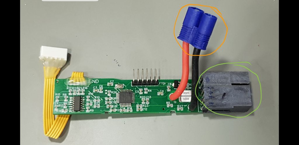
5 January 2020: designed some initial PCB’s – now with individual cell measuring and current sensing.
(I hope to start selling them as a product before March 2020)

15 December 2019:
Currently handled I2C requests (all that Solo is requesting:)
0x08 TEMPERATURE
0x10 FULL_CHARGE_CAPACITY
0x1C SERIAL_NUMBER
0x0F REMAINING CAPACITY
0x23 MANUFACTURER_DATA
0x28 CELL_VOLTAGE
0x2A CURRENT
This is an early version of a BMS for any 0-5v/cell chemistry 4-cell pack for ArduPilot.
Right now, it is more correct to call it an BMS emulator, than a BMS.
A final product would measure individual voltages and the actual current. I started this way because it does not require a custom PCB and a minimum of discrete components.
This early version does handle all the communications, and makes the autopilot set the actual capacity (9Ah), reports voltage, and calculated individual cell voltages.
It does also calculate and report remaining capacity by doing a 15-point linearization and then interpolating a “voltage_to_capacity_table”. This method is good enough once one knows the battery characteristics and fly at about the same current later.
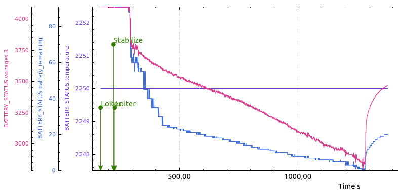
Test Flight1:
I did not wait for the 4S3P Li-Ion pack to charge fully. (Samsung 3Ah 18650-30Q cells) The outdoor temperature was about -5°C, batteries. Flight time was 17 minutes. With GoPro4Black + the brushless 3DR Gopro gimbal. The battery pack was 677gram. Included in that weight is 22gram that is the BMS microcontroller PCB, Solo battery connector and wires/connectors to battery.
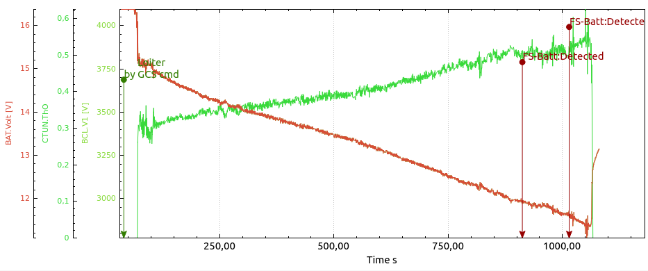
The predicted SoC percentage (blue) is clearly not perfect (yet) it was good at the end, not at the beginning, but that is not a problem, as it is easy to change by modifying the table.
Notice that it can still climb at as low as 10.5v , not exceeding 70% of throttle.
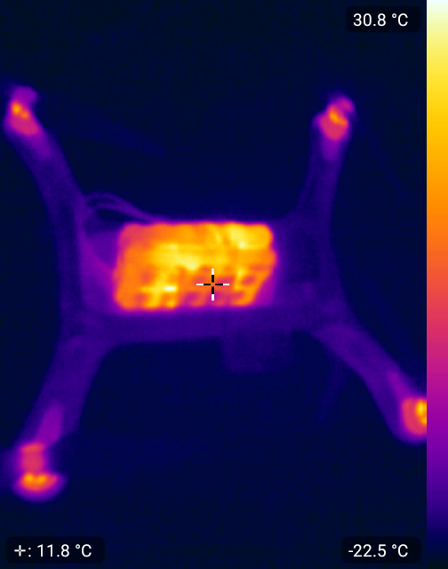
Post-flight thermal image: (somewhat affected by some kapton tape on the battery pack.)
TODO / Future:
Given enough interest, I plan to make a fully standalone BMS that can be user-customized to any chemistry, (min/max voltages) and so on.
With balancing, real current sensing, fuel gauge etc.