13 May 2018: Firmware Ver 1.9 is out ! , see below. 🙂
ArduPlane , ArduCopter (and similar Ardupilot projects) use Mavlink for telemetry, while Graupner has a very useful telemetry system HoTT.
This device provides all the data Graupner’s EAM(Electric Air Module),GAM(General Air Module),GPS,Vario modules offer.
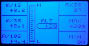
Data that Ardupilot does not provide in it’s telemetry stream: (distance and direction to home, 1s,3s,10s vario-data and battery cell voltage/min/max voltage) are calculated in the device.
ArduCopter and ArduPlane are detected automatically, and correct mode-names will be displayed.
The GPS position format is converted from DD (degrees,decimals) transported by mavlink, to the DM (degrees, minutes.decimals) as expected by HoTT, direction and distance to home is also calculated, (it’s not provided by AP).
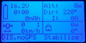
Note the “DIS.noGPS …” = Disarmed, no GPS Fix, mode is Stabilize.
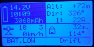
This is the inverting/flashing voltage background, (also audible warning) for “Battery Low”.
Arduplane & Arducopter modes are visible as text. Future/unknown modes as number.


Real status messages:
The device enables HoTT to display actual Ardupilot system messages, longer messages are split and displayed as two interchanging parts. like this:


Bootup messages:

Should a prearm check, or arming check prevent you from arming, you will know exactly what the problem is.


For a quick overview over all messages you may see, here is a dump of messages found in ardupilot source code
This method is superior to FrSky telemetry, which at best, tries to recognize, and encode the messages, then a .lua script in the transmitter is supposed to display a corresponding/equivalent message. That method works only for known messages (depending on firmware), and things can get “lost in translation”.
This device, however, just display text as-is, and thus can display new and future messages as well as composite messages that may contain variables or debugging info.
Firmware upgrade:
There is an custom bootloader on the device, it’s possibly to upgrade it using a standard FTDI cable and the avrdude tool (exists for Linux,Mac,Windows & more).
FTDI cable, with extra pin header.

Insert pin header into FTDI cable, the protruding, short pins will fit into the Mav->Hotts six pins on the edge of the PCB.
The upper & lower of the six pins on PCB, are marked BLK (black) and GRN(green) – make sure that matches the orientation of the FTDI cable. (reversing does no damage)
To write the new firmware you will need avrdude application.
On Linux, it’s installed by: “sudo apt install avrdude”
The firmware upload command is:
avrdude -patmega328p -carduino -P /dev/ttyUSB0 -b115200 -D -Uflash:w:Mav2Hott.v1.9.hex :i
/dev/ttyUSB0 is most likely correct, the number will be higher if you have more than one USB serial device
If you are using windows, replace /dev/ttyUSBx with COMx , also, in windows you’ll need some FTDI drivers.
Please note that the programming protocol is arduino compatible just enough to make it work with avrdude, but it’s not really arduino.
Firmware 1.6
- Audio warnings for mav_severity >2 only (now that severity is fixed)
Firmware 1.7
- Fixed and expanded low/critical battery threshold
Firmware 1.8
- Relaxed audible warnings
Download: Mav2HoTTv1.8
Firmware 1.9
- Updated flight modes for ArduPlane & ArduCopter to include modes from current master (next release) of those.
Download: Mav2HoTTv1.9
Low battery and critical battery alarms;
- 3s Warning 10.8v , Critical 10.2v
- 4s Warning 14.2v , Critical 13.6v
- 5s Warning 18.0v , Critical 17.0v
- 6s Warning 21.5v , Critical 20.4v
Warning inverts/flashes the part of the display that contains battery information, and give relaxed audible warning. The LEDs, if connected, are blinking diagonally (only warning/critical state does that)
Critical battery level does the same, but the audible warning is more intense, and rapid, LEDs are flashing diagonally very fast.
Detected cell count can be seen as number of displayed cell-voltages (which is calculated from initial battery voltage)

most useful information at a glance, by using just heading, and flying so it gets equal to gearing to home – you can fly home even without seeing the model.
Mavlink mode-controlled LED controller.
There is no need for HoTT telemetry to be sent, only read the Mavlink protocol input, for the LED controller to work.
For ArduCopter, there are four outputs for leds/strips (non-amplified, so you will need a transistor if you wish to use them with more than a few LED’s)
The blinking patterns are different for each mode, but follow this system:
- Stabilize = solid on
- Alt-hold = short off-time on rear leds
- Autopilot modes does not have solid front light, indicating that AP is on
- Diagonal blinking patterns are used for errors, noGPS fix, low battery, and anything else that may be reported over 3DR radio/mavlink as an critical state.
- Warning/Critical blinking ignores LED Switch function.
The outputs are on pin 7(RearLeft),8(RearRight),9(FrontRight),10(FrontLeft) . – they will flash diagonally in case of critical events, and different patterns depending on mode/situation , GPS fix and so on.
LED Switch function: if pin2 gets a PWM betwen 900…1200µs , the LEDS goes dark except if critical condition, or a battery warning – in case of which, the PWM will be ignored, and LEDs will flash anyway.
Safety:
The device does only read mavlink, (it’s connected to telemetry TX pin) , fed with power from receiver or telemetry port, and so it is unable to influence the operation of the autopilot in any way.
Connecting:
- Voltage: GND and +5v goes to Pixhawk/APM or Receiver.
- Connect RX pin to your 57600 baud telemetry TX pin on Pixhawk/APM
- Connect Pad5 to your HoTT receiver’s telemetry input.
If you wish to power it from Pixhawk, It’s ok. This would be the connections then:
- Telemetry connector(of your choice), Pin1 (red wire) – goes to VCC on the device
- Telemetry connector Pin2 goes to device’s RX pin
- Telemetry connector Pin6 (last one) foes to device’s GND
- Pad5 on the device, is connected to you HoTT RX’s “T” input.
This is an example of a possible connection: Usually, people connect it in paralell to another Mavlink device, like OSD or radio, so there is no need to purchase a DF13 connector.
note that the device comes without wires, I assume most people do have a old servo cable, and are better off installing the length actually needed.

Troubleshooting:
- If HoTT display (in the mode that display text) says NO MAVLINK … check mavlink
- If you only see mode, no other info – check the parameters below, used to tell Ardupilot how often to send the different messages as suggested below:
- SRx_EXT_STAT = 2 ; 2Hz battery voltage, current and capacity GPS,fix .RAW GPS position, velocity, altitude
SRx_RAW_SENS = 2 ; gives 2Hz pressure, and temperature.
SRx_POSITION =2 ; position mixed with accelerometer & barometer data
SRx_EXTRA2=2 ; heading, baro altitude, climb/descent rate
SERIALx_PROTOCOL = 1 ; set the serial/telemetry port to Mavlink protocol
Buy Mavlink>HoTT interface ($60)Shipping :
(Cart will appear below)
It is working very well out of the box.
No hick-ups.