3DR Solo iMX6 as video and telemetry link

3DR Solo, have a great onboard computer, the IMX6 runs Yocto Linux : link to the Linux source: https://github.com/OpenSolo/imx6-linux

Among it’s best features is the HDMI-in, USB, and mini-PCIe port which can easily use rather powerful MicroTik router/Wi-Fi modules.

I reverse-engineered the remaining pins, as only the 3 and 6 pin headers were known to the community.|

Battery 7-24v, is the main power source.
+5v input does not seem to be essential for normal operation.
First USB host (D+,D-) is a normal USB2.0 host, compatible.
SEL(select) and OE(output enable) are two GPIO pins used by Solo to select where this USB host is connected: During normal operation the OE control if it is connected to any device (or not) and SEL controls if it is connected to the Cube (for firmware upgrade via bootloader) or the gimbal bay connector.

Unless you need more than two USB devices, you can ignore SEL and OE, and just use D+/D- for the USB host as usual.

Then there is the USB-OTG port. If you pull down the “Sink to GND…” pin, then the USB-OTG port becomes another USB host port. Otherwise, the USB-OTG port is in OTG mode, and will act as a slave/device – so that you can connect it directly to another host(usually a computer) This pin is not routed to anything on the Solo main board I tested.

The default onboard Linux is compiled only with FTDI and CDC-ACM (Communication Device Class – Abstract Control Model) profile, so it will instantly work with all kinds of Arduino/STM32’s that normally show up as a ttyUSB or ttyACM device.

DSM outputs a Spektrum RC control signal from the Solo Controller, it is optional to use it.

Finally, there is the usual RTS, CTS, RX, TX that is used for MAVLink telemetry, the hardware flow control is optional.

There is one more pin “not used by Solo” that is not routed anywhere, but on the iMX6 it is certainly connected to something, maybe another GPIO

As-Is, you can take out the iMX6 from a Solo, and use it and a Solo controller with any MAVLink source.
If no MAVLink stream is presented, everything else will still work, but the controller will auto-sleep after 10minutes or so. This could probably be easily fixed/changed in the controller’s software.

3DR Solo Cube 5v modification (Run ArduCopter safely with stock cube)

Update: As of Arducopter 4.0.0 for Solo, the motor slew rate is available, and this mod is NOT required if you are happy to use slew rate.( which gives a little less responsive copter, lust like the original 3DR fix.)

3DR Solo Cube (Pixhawk 2.0) outputs 3.3v PWM, the IO buffers run off 3.3v on both sides, while they are perfectly capable of delivering 5v.  Using 5v is safer when using 3DR Solo firmware with PWM slew rate, and required for ArduCopter code on Solo.

The simple solution is to purchase “Green cube” (usually sold out)  or modify Pixhawk 2.1

The alternative solution, is to modify Solo’s Pixhawk 2.0 Cube.

This does require some soldering skills, and can be done by any semi-decent repair shop if you cannot do it yourself.

(The width of the buffer chip is 4.5mm)

The two first images show two different PCB layouts of the Pixhawk 2.0 cube, so everybody should recognize, and stick to one 🙂

Open the cube, and locate the rightmost buffer ic. (TXS0108E marked YF08E)

Desolder the buffer (here seen on another PCB layout):

Cut the trace that feeds the upper left pad:

Re-solder the buffer:

Attach a thin wire to the pin. (provide 5v to the buffer’s VccB)

The other end of wires are routed to the clearly labelled 5v pad in the upper right corner of the Pixhawk2.0 :

Finally, clean and cover wire using conformal coating, to prevent vibrations to damage it: (UV inspection below)

Congratulations, output 1…8 output is now 5v.

Final note: the UV inspection picture picture shows another buffer, not used for PWM, the photos are taken on different occasions, and while batch processing many, not only one, so the time is not 30minutes between desolder and resoldering one device as timestamp may suggest.

Should you use a professional to do this job, it should take <15 minutes.

Modified files for uploading using Solex (Just copy into /Solex/download/package)  – The only modification is to make Solex ignore the fact that the modified cube still runs the old 3DR fork of ArduCopter.

Once you upgrade to the 3.5.2 I provided here, you can continue to upgrade to newer versions using SSH /Solex and/or OpenSolo as if you had the greeen cube.

(2) Wipe Pixhawk Firmware for 5v mod

(3) ArduCopter 3.5.2 Firmware for 5v mod

(There is nothing special with the ArcuCopter build itself, only the )

Double DIN car computer

It’s long time since last time I published a new buildlog/project.
My new car needed a decent stereo,  it had a “iProduct” interface, but I needed something better.
Unlike my previous car computer projects, I did not wish to install an amp + carputer in the trunk, and run VGA,USB and speaker cables forth and back. I wished to have everything integrated in the dashboard.

The idea was to build according to ISO standard, then use a Toyota<>ISO-harness adapter.
Using the ISO-Toyota harness and integrating an amplifier also makes it easy to control the car’s active sub kit and active antenna, without modification.

Analysis of the resistive buttons connector in Avensis
Picture
This is the control module interface documentation, a RJ45 connector between computer & external controls.
Picture
This is the control panel itself, controls power mode (always on/always off/follow ignition) camera select and reset switch built into the ashtray,(usually closed)
Picture
Lilliput 629 (7″ touchscreen) disassembled
Picture
The resulting analysis of the proprietary connector of the display controller. Cables with proper motherboard connectors are now soldered directly to it.
Picture
The Lilliput needed to have some shielding cut off to fit better inside the (far from perfect) Double-DIN box
Picture
The display’s edges needed to be padded, to prevent the double-din frame from “touching” the touchscreen area.
Picture
Display, and display controller installed, IR sensor and buttons relocated.
Picture
Don’t repeat my mistake, while waiting for this motherboard, I built proper 2,54 connectors for VGA,USB,Audio and so on, just to discover the pin headers on this motherboard are 2.0mm !
Picture
Circuit for relay control. (provides power to display, amp, external amp(active sub), and antenna output).
Picture
Motherboard+PSU installed, the hard-drive is below motherboard
Picture
The amplifier is now installed (built around a TDA7850 (4x~50W) plus BA3121 ground isolation amplifiers.).
Picture
Radio module installed, The blue cable in the control port simulates the “usual” control-panel configuration for lab-use (follow ignition) and use reverse camera
Picture
That’s it, ISO connector compatible device. with internal radio, and amplifier.
Picture
Installed in car, displaying reflection because it’s off.
Picture
Running Centrafuse
Picture
I also modified the “hibernating” screen with a custom logo – removing windows logo feels good, looking forward to the release of Centrafuse for Linux. Picture

Sublight – Powerful SCUBA lamp.

Night diving and wreck diving requires a good torch. When I asked for advice on buying a torch, most divers I told me that “30Watts are great , 50Watts are insane , and anything above is not really necessary…”

If it’s worth doing, it’s worth overdoing.  I started with interpreting what they said , It sounded to me like this: “30Watts are OK , I have it because I could not afford the 50Watts , anything over 50Watts is what I would like to have”

So… what I “needed” was :

  • 225Watts … (3 x75Watt bulbs)  
  • battery time of at least two hour at reasonably high intensity…
  • Variable intensity
  • >20Khz PWM (Pulse Width Modulation) to keep high efficiency and no noise.
  • Internal 28Volt DC-DC converter to improve efficiency of Power MOSFET’s .
  • Multiple bulbs (3), just in case one dies – there are still two left.
  • Voltage monitoring.
  • No disassembly required for charging.
  • Nice software with SOS and maybe a bottom-timer.
  • Self adjusting intensity (not implemented yet)
  • Low battery warning and battery capacity prediction. (not done yet)


So , the project resulted in:
Acrylics pipes with 22mm acrylics ends , with O-rings , 4Mhz RISC Microprocessor that works at 4-5 volts , 28Volt DC-DC pump , 2 optically isolated PWM outputs that uses the 28volts to control 50Ampére low-drop power MOS-FET’s so fast that the MOSFET’s does not require any cooling as they “never” are in linear state. A 2×16 Character LCD display had to be added.

There are no moving parts, the 3 buttons and on/off are magnetically controlled and does not represent a weak point (or should I say leak point ?)  


here is the battery case : two 12Volt 6,5Ah batteries in parallel gives 13Ah ! (could be 2×7.2Ah , but I 6.5Ah was all I had).

Here is the torch ,

the display is showing voltage and intensity. as soon one bulb is 100% on , the other 2 starts helping , that’s to distribute the bulb-burn-time so their life length will be different. those are 3x50Watts “Osram Decostar” (1×10º , and 2×24º)  halogen bulbs ,just because I did not got any 75Watts , of course , the electronics will handle 3x75W (225Watt)

The LCD display is back-lit , (green/blue) , and looks very nice under water. Now booting …


because of the massive intensity of the light , the camera could not do better , the LCD is invisible , It’s normal daylight in the room but “seeing” this bright light source , the camera made this picture so dark.


The Freeware

The design/circuit  should always be treated as freeware, you might build as many as you like , even for your friends.

The author (me) must always be credited as the author.

The compiled program is here. , It is possible to buy preprogrammed controller from me.

The schematics: (right click the picture below and “save target as”)

A little description , it should be everything you need to know:

  • U$3 is the LCD connector , any HD44780 compatible LCD goes , at least 2×16  characters.
  • PADLAMP1 is the pad (output) for lamp1 , padlamp23 is is for lamp 2and3
  • JP2 is the switch/button connector
  • use IRFZ44 or better power MOSFET (BUZ 11 is used on schematics by accident) – they are pin-compatible.

FAQ:

Q: Do you have the container plans ?
A: No ,I just found some material that would fit the batteries worked on it.

Q: Is there a PCB layout ?
A: Yes , I designed a two layer PCB ,but never etched it.

Q: Where did you found the O-Rings you needed ?
A: A hardware store sold them as meter-ware with a special glue, then I made the O-rings I needed.

Extra fan sensors for Motherboard Monitor

how to add 4..16 extra tachometers to your computer

Motherboard Monitor by Alexander van Kaam is a great freeware that uses hardware monitoring chips found on most Pentium and all newer motherboards. MBM will detect and use the circuit described below.

Some motherboards have 4 monitored fan connectors ,others have only 2. They all have one thing in common: the SMBus.

Want to add 4, 8, 12  or 16 more fan sensors ?

One of my computers is a fulltower with 14 harddrives, 12port hardware RAID controller , SCSI adapter and is cooled by 5 fans in the cabinet + one on CPU , plus 2 in PSU and 2 in drive cage.

So I needed to to monitor more fans.
I choose the MAX6651 16 pin QSOP IC. (datasheet)

You can get one at http://www.maxim-ic.com/
MAX6651 offers 4 fan monitors (tachometer), and five programmable I/O ports.and voltage control that could be used to control fan speed.

Schematic:

Resistors 10K

Please add a 10nF capacitor between GND and VCC near the chip.

ADD is the pin that sets the IC’s SMBUS address, there can be up to four MAX6651’s on the same bus and the address is set by:
-ADD Connected to GND
-ADD Connected to VCC (+5V)
-ADD Not Connected (floating)
-ADD Connected to GND using a 10K resistor.

SMBus Connector:

Motherboards SMBus connector is 5-pin and is configured like this:
1-CLOCK
2-(not used)
3-GND
4-DATA
5-+5Volt

Most decent motherboards have such connector, if you cannot find it, or your motherboard do not have it, thengo to my “locating SMBUS” page for instructions.


Some additional info from the author of MBM:

The MAX6651 is a sensor chip only for fan readout, this sensor chip is not automatically detected by MBM because it has no device ID and it can be located on an address which a normal sensor chip uses, so if I where to auto-detect it many users would suddenly get this sensor chip in their fan list while they don’t even have it

Edit the MBM 5.ini file and find the [ADVANCED] section, add the line MAX6651=1 this will make MBM scan for it.

Please understand that the fan divider on this sensor chip counts for ALL fans and thus should be set the same for all the MAX6651’s of 1 chip found. The last one MBM sets when starting up is the one that will overrule all others

example:

Fan 1 : MAX6651-1-1 : divider 2
Fan 2 : MAX6651-1-1 : divider 4
Fan 2 : MAX6651-1-1 : divider 8
Fan 4 : MAX6651-1-1 : divider 4

for all fans MBM will set the divider to 4 since Fan 4 has it at 4.

The challenge….

…Is to connect the small QSOP package MAX6651 comes in.

You should be happy MAX6651 is so small , with that little mass it picks up temperature changes really quick (local sensor in huge packages is always sluggish)

So all you have to do , is connect those pins , each pin is 0.25mm wide, and there is one pin each 0.6 mm.
That is : “on less than 5mm there is 8 pins to solder”.

You need a soldering iron with a small tip.

SMBus uses only weak (20mA) open collector outputs. It’s not possible to destroy I2C or SMBus by short Data and/or Clock to GND or VCC or to each other.

The easy way….

You can order a prototype QSOP PCB http://smt-adapter.com/ (*) that have large terminals and are easy to work with .

*Thanks goes to Brian Macomber for providing the link.

Some Pictures….

just a test computer – observe the “Fan 4…..Fan 7”


The black 4-pin connector is the “floppy power” connector – it’s there to provide power (+12volt) to the fans.
The double green connector is the SMBUS connector that goes to the motherboard – there are two of them (above each other) to allow chaining of more SMBUS devices , like even more fan sensors or temperature sensors.


FAQ:

Q: how can I make a fanbus that is able to control the fan speed/(voltage) ?
A: The MAX6651 have several outputs, but only one is “almost” suitable for controlling speed. To be able to smoothly control the voltage to each fan, a simple D/A output is not enough.


Additional Info/thnx:

Per Ullman – shows you here how he build this project by connecting to the RAM DIMM sockets, rather than soldering on the DIMM’S.

 Thanks to:

Alexander van Kaam – not only for MBM, but also for quick help and additional info.

Adding extra temperature sensors for MBM

How to connect more temperature sensors to Motherboard Monitor

Motherboard Monitor by Alexander van Kaam is a great freeware that uses hardware monitoring chips found on many Pentium and all newer motherboards. MBM will automatically detect and use the circuit described below.

Some motherboards have 3 external  temperature sensors ,other have 3 internal.
Some can monitor negative voltages , other does not. They all have one thing in common : the SMBus.

Want to add 5 , 10 or 45 more temperature sensors ?

I am using water cooling and “needed” more than my 3 temperature sensors (as one is on motherboard and the two others monitors the two CPUs) , after looking into the wide sensor support MBM offers I decided to try to attach another chip to the SMBus (Intel’s version of Philips’s I2C multimaster bus).

 MAX1668 16 pin QSOP IC. (datasheet)


You can get one at http://www.maxim-ic.com/
The 1668 offers one local (on chip)  sensor and 4 diode-coupled-transistor sensors.

Transistor-sensors is what you want , a little more work , but more accurate , and they already exists in CPU’s , GPU’s and other IC’s with internal sensor.

The schematic is very easy , and needs few external components.

(*)=  2200pF capacitors –not needed if you use twisted pair wires.
(*)=  +.1uF capacitor – used for decoupling.
(*)=  200Ohm resistor – can be omitted (just use a wire instead) as you use only 5volt (SMBus)
(*)=  10K resistor –not needed, as you are not using ALERT output.

The sensors , (transistors) can be BC547 with basis connected to collector. they work only when connected correctly , there is no risk to damage anything if reverse-connected, the sensor will not work until corrected..
BC547 is a very old , cheap ,  and small transistor , and it’s body volume can be reduced to less than half with a Dremel-tool. (the copper/silicone part is really small)  There is no need to use any expensive transistors , all that really matters is that it’s a silicone (not germanium) transistor , and not a darlington coupled one.


Addressing:

Each MAX1668 have an 7 bit address that is unique to this SMBUS device, and no other similar device will have. The 3 LSB (least significant bits) of this adress can be changed by ADD0 and ADD1 pins.

If you want to have more than one MAX1668 on the SMBUS, each of them needs and unique address.

The table below shows the 9 possible configurations, and where to connect ADD0 and ADD1 pins:

ADD0 ADD1
GND GND
GND Floating
GND VCC
Floating GND
Floating Floating
Floating VCC
VCC GND
VCC Floating
VCC VCC

(Floating means “not connected”)

  …YES , It means you can have nine MAX1668 on the same SMBus at the same time with no problems , just make sure each have it’s own unique address. Just choose an address , MBM will detect any.

Any unused sensor inputs should be shorted (to prevent floating) , and shorting one tells the chip that sensor is not in use.

SMBus Connector:

Motherboards SMBus connector is 5-pin and is configured like this:
1-CLOCK
2-(not used)
3-GND
4-DATA
5-+5Volt

Most decent motherboards have such connector, if you cannot find it, or your motherboard do not have it, thengo to my “locating SMBUS” page for instructions.

The challenge….

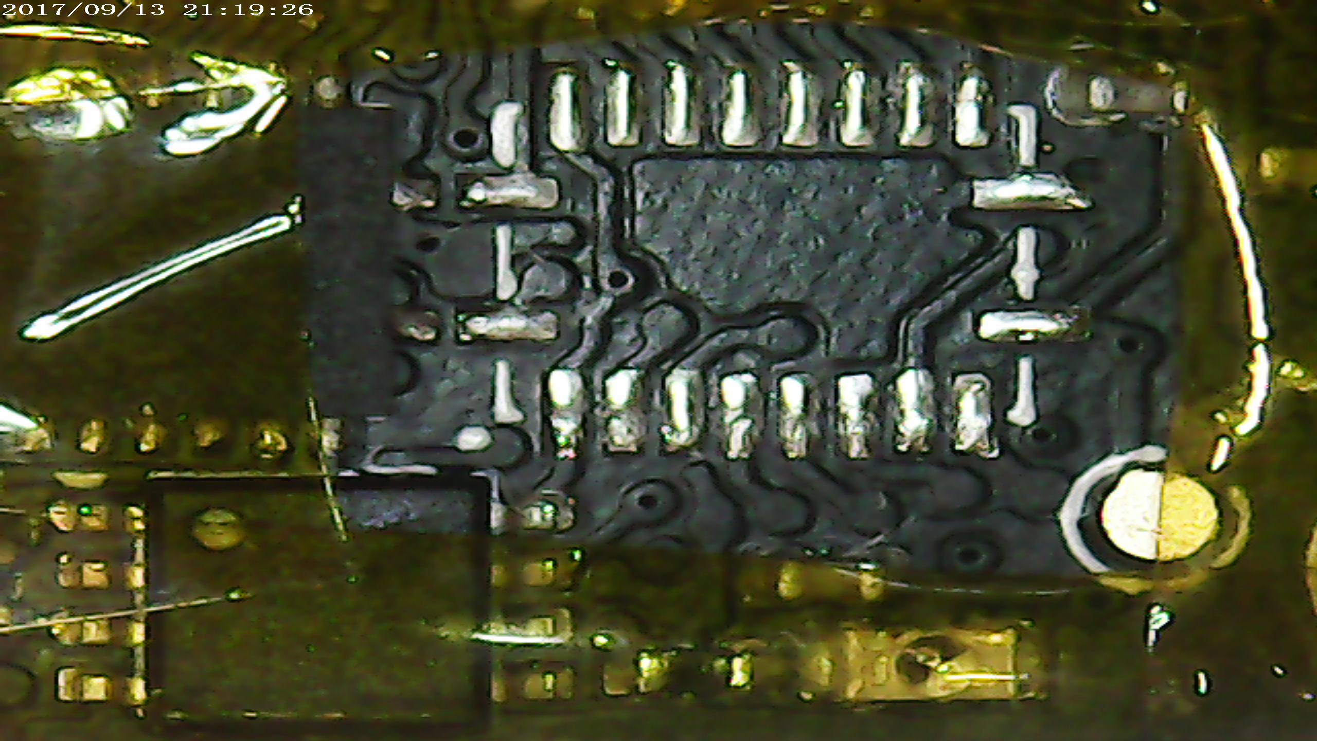
…Is to connect the small QSOP package MAX1668 comes in.

You should be happy MAX1668 is so small , with that little body it picks up temperature changes really quick (local sensor in huge packages is always sluggish)

So all you have to do , is connect those pins , each pin is 0.25mm wide, and there is one pin each 0.6 mm.
That is : “on less than 5mm there is 8 pins to solder”.

SMBus uses only weak (20mA) open collector outputs. Theoretically it’s impossible to destroy I2C or SMBus by short Data and/or Clock to GND or VCC or to each other.

The easy way….

You can order a prototype QSOP PCB http://smt-adapter.com/ (*) that have large terminals and are easy to work with .. or you might look for it at www.elfa.se  , if you get such pcb , then just place the QSOP package on the PCB and heat up the terminals , no soldering needed.

*Thanks goes to Brian Macomber for providing the link.

Some Pictures….

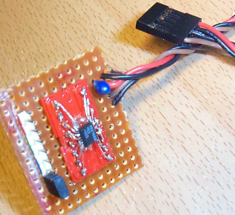
…This is how mine MAX1668 board looks , the chip is mounted on a DIL16 socket, the 8 pins to the left are 4 connectors  for external sensors (you can see they are color-coded) , the last one has a jumper , a jumper instead of a sensor tells the chip that this input is not used , and it returns 0°C.

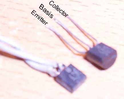
This is one of the “sensors” , a modified BC547 transistor , as you see it’s less than half size of a normal BC547 , I’ve made even smaller ones now. The transistors should be “diode-coupled” – it means their basis and collector is shorted.  One wire goes to the basis+collector , the other to emitter.


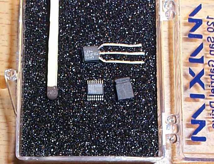
This picture shows the size of MAX1668 compared to some known objects , (BC547 transistor and a jumper)

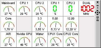
“Air” – is the local on-chip sensor
“Nvidia GPU” is a transistor-sensor on the back side of PCB where the GPU is.
“Water” is usually water temperature , , showing maximum temp , because it’s disconnected to demonstrate what you see before sensor is correctly connected

Thanks to:

-Antonio , for reporting an error on this page  , and helping with a fix.
-Chris, for grammar check.

-Lee Hollis – for showing people how he accomplished this project

-Andreas Lenz – for showing people how he did it, in German
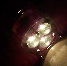
“FreeFlow” Valve for Rainmaker

…That’s the name I’ve chosen for this mod.

Most people agree that the original Rainmaker valve does not provide optimal flow , there are few aftermarket valves that should improve the flow , but none of them impressed me , so I made my own , with absolutely highest flow possible.

To the left , the original valve body , to the right , my version.


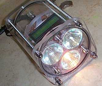
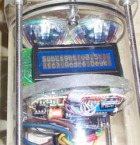
I made two different .,,,

Sorry , but I’m not selling these , too much work , …. unless I come across a cheap CNC machine  🙂