BMSOne 2 – Universal 2S-6S BMS for ArduPilot

BMSOne (4S) $42

BMSOne (5S) $42

BMSOne w/XT60 $47

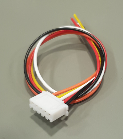
20cm balancing cable JST-HX $1

[show_wp_shopping_cartDISABLED]

OUT OF STOCK – DO NOT ORDER YET – more will be available in August

Description:

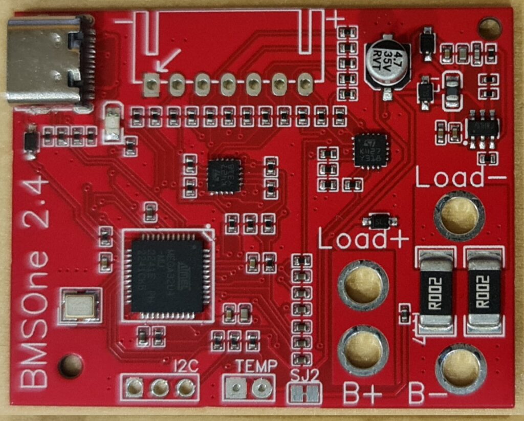
All new orders are delivered with hardware v2.4 , USB-C, internal temperature sensor.

This device is not limited to 3DR Solo, but build to work with any 2S-6S battery and ArduPilot.

Provides a real state of charge, and individual cell voltages.

3DR Solo can use any Li-xx battery in 4S to 5S configuration.

The PCB is less than 50x40x9mm (the balancing connector is the highest component) The weight is only 7.9g

The device in 4S, 5S, and 6S configurations is exactly the same, fully populated with all components. The only difference is the balancing connector.

Super-Simple, Plug & Play version:

If you dislike configuration, finding a suitable battery, etc.. please see the super-user-friendly version made by some nice people at: https://jonbrotherton.fws.store/BMSOne_Plug_and_Play/p5973142_21044679.aspx
Basically: It gives you a simple plug-and-play solution, none of the setup/configure/install/mount stuff.

4-6S Support with older ArduPilot:

The older ArduPilot and Solo support 4S batteries.
If you connect BMSOne with 5 or 6 cells to an older ArduPilot it will automatically spoof a 4S battery consisting of four of your lowest-voltage cells – while providing the full 5/6S voltage of your pack.
This way, it is perfectly backward-compatible, and safety is maintained by always reporting the lowest cells.

4-6S Support with newer ArduPilot:

Newer ArduPilot can use the 4-6s capability of BMSOne.
You will see all cells.


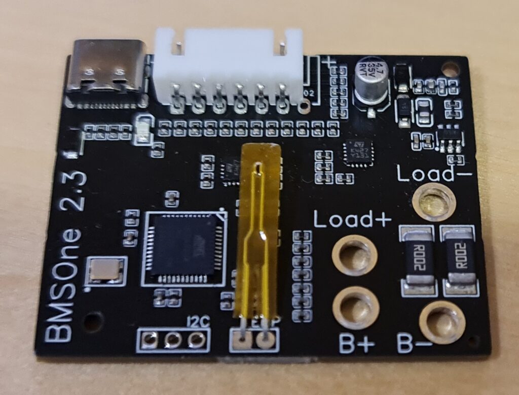
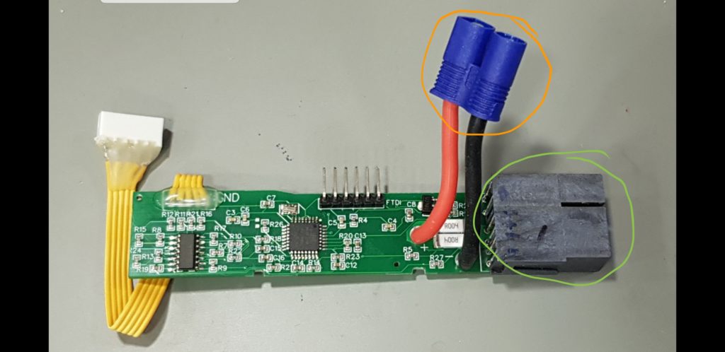
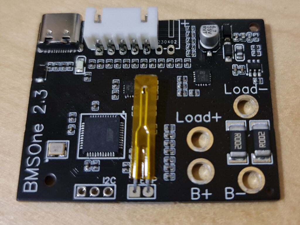
This is the BMSOne:

The backside. B+/− is where you connect the battery, if you do not use a Solo power connector, (or not a Solo) – then the output is +/- and SDA/SCL is clearly labeled.

Configuration:

Configuration, like firmware updates, is done using the USB-C port.
Configuration commands in BOLD:

When you connect to it at 115200kbps, (8N1) and power it up, you will see:
BMSOne v2.0
Set the capacity of the battery in mAh using the command:
SM10000
it will respond:
Set capacity: 10000
Now, you have defined a 10Ah full capacity.

The device can provide remaining capacity information based on one of the methods:

S0 //remaining capacity is estimated based on voltage.
S1 //remaining capacity is reported based on mAh consumed (assumes you start with a fully charged battery of defined capacity on boot)

S! // No thermistor, fake 22.5°C temperature
SH //100K Thermistor
SW //write configuration to flash – until you do this, all your changes/calibration are temporary and can be reverted by rebooting the device.
SR //read config from flash (it happens on every boot)
SS //Show config
SD //Show internal data

S~ // erase EEPROM (reset the configuration to firmware defaults/factory reset)

Displaying Configuration:
Voltage table: 104, 110, 113, 116, 119, 122, 126, 129, 132, 135, 138, 142, 145, 148, 168,
Capacity table: 0, 4, 12, 20, 29, 37, 45, 53, 62, 70, 78, 86, 95, 99, 100,
SoC by Voltage
Cell voltages(mV):3727,3731,3739,3744
Pack voltage(mV):14941
Current (mA):-152
Full capacity: (mAh)10000
Remaining capacity by Voltage: (mAh)9900
Remaining capacity by Current: (mAh)10000


Calibration procedure.

Important: since September 2023 each device is calibrated individually prior to shipping, do not calibrate, or use S~ command unless you plan to do the calibration.

With a battery hooked up, you can measure its cells, then provide a command like this: the numbers are voltages in millivolts.
let’s say you measured 3.256v, 3.231v , 3.255v and 3.263v then enter:
SC3256,3231,3255,3263 // calibrate cell voltage in millivolts for 4 cells.
If you can’t measure with 3 digits, – let’s say you can measure with lower precision “3.21v” then enter “3210”

SI10220 //Calibrate current sensor, value in mA “SI10220” = 10.220A
Again issue the command with a known current flowing through the device. It is better to calibrate while sensing 10A than 100mA.

Capacity by voltage linearization table:

For Li-ION:

SV 10.4, 11.0, 11.3, 11.6, 11.9, 12.2, 12.6, 12.9, 13.2, 13.5, 13.8, 14.2, 14.5, 14.8, 16.8 //set 15-point percent linearization table
SP 0, 4, 12, 20, 29, 37, 45, 53, 62, 70, 78, 86, 95, 99, 100 //sets 15-point percent table.

So by the example above 11.3v (third value) equals to 12% , (while 11.5v will be interpolated to a little less than 20%.

For Tattu 4S1P 5200mAh 35C

Thanks to Gary Pang’s generous donation of such battery, here is a configuration for this battery:
S0
SV 14.0, 14.1, 14.2, 14.3, 14.4, 14.5, 14.7, 14.8, 14.9, 15.0, 15.2, 15.3, 15.8, 16.0, 16.8
SP 0, 8, 21, 27, 41, 49, 57, 64, 72, 80, 85, 88, 98, 99, 100
SM5200
SW

ArduCopter 4.x battery safety settings:

These settings are for ArduCopter 4.x , which you should be using with OpenSolo 4.0 or newer. The BMSOne does work with OpenSolo 3 and AC3.6.x too, but it does not work with the original, old, forked 1.5.x versions of the autopilot, (nor should you fly the old versions)

If you use S0 mode(default), set low and critical-voltage thresholds:
BATT_LOW_VOLT
BATT_CRT_VOLT
If you use S1 mode(capacity based), also set low and critical-capacity thresholds:
BATT_LOW_MAH
BATT_CRT_MAH
Finally, these parameters define what action is taken:
BATT_FS_LOW_ACT
BATT_FS_CRT_ACT

SoC Voltage mode explained:

S0 = State-of-Charge by Voltage
This mode is beautifully simple and reliable, as you can use any number of battery packs, with the same type of cells, and have perfectly fine SoC estimation (see battery percentage drop)
The advantage of this mode is that it works by voltage under load, so you can have one BMSOne and any number of packs, and any state of charge on those, and still, it will “just work”

We all remember how fast the remaining capacity drops on a Solo battery at the end, 20% can fall to 3% within one minute.

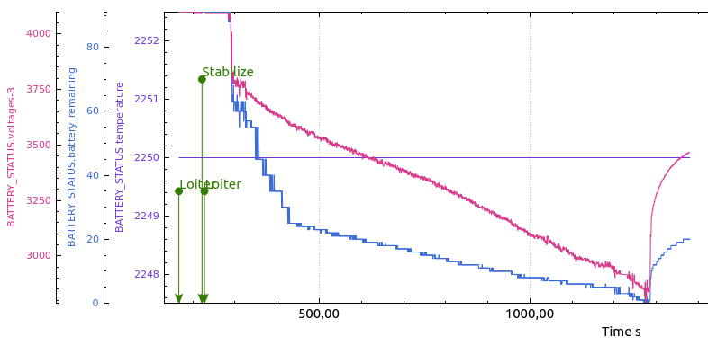
The first graph is made using these packs’ first flight.
It estimates energy as consumed a bit fast in the beginning, then just a little faster after 19/20 minutes.

Then the voltage/capacity table is corrected.. and watch the second graph, beautiful linear estimation, no surprises there even as the battery gets to 2.5v/cell.

Another aspect of SoC by voltage is that it is most accurate when at normal cruise/hover. During a fast climb, the voltage will drop, and while climbing, you will see a lower estimate, and during a fast descend, you will see a higher estimate.

21minute flight example:

(I flew in bad wind conditions, now I see that the flight had the 4.0.3 PID issue that surely affected the flight time in a bad way)
4S3P Samsung INR18650-30Q (12 cells) 620grams with BMSOne.
GoPro Gimbal with Gopro 4 Black. AUW 1950g
Cells bought from Banggood (please observe that this is not a referral link, I get no kickback, nor can I guarantee the authenticity of a later batch).

1297 sec (21min) long flight in light rain and 2-4m/s wind.
I landed at 2.6v/cell, yet the manufacturer’s datasheet use 2.5v as the cutoff.

How to make a linearization table:

Let’s say you have a battery with given chemistry that you want to charge to 16.8v max and fly down to 14.0v minimum voltage. None of the known tables work well for it.

On a day with calm or no wind, fly slowly or hover well out of ground effect.
Monitor the voltage of the individual cells and fly the pack down to the desired 0% state, for example, 14v.

The most important part is not to affect the discharge curve by hard flying or rapid climbs/descends. You want to see the pack’s normal voltage drop under normal load.
Get the log from the Solo, and plot BAT. Volt using APMPlanner2 or similar tools.

Now imagine, or draw some number of data points you want to read out, they can be spaced out by time on the x-axis, or better, you can increase density where the voltage is less linear as illustrated with red lines below:
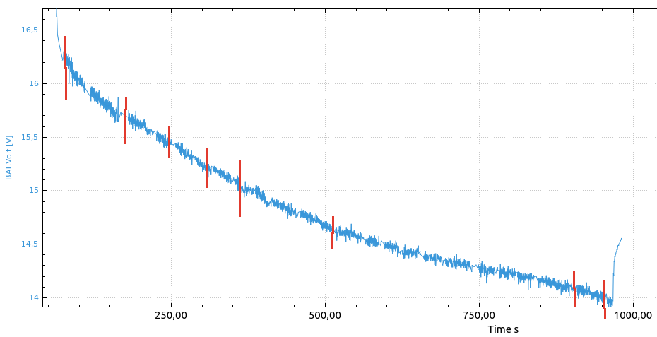
Your first data point would be full pack voltage 16.8v, 100%
The next one, the voltage that is measured right after takeoff, you can see the voltage drop to 16.25v under a given load, but you know it is still full, so the next data point is 16.2v, 99%
The next data point may be read out at the second red line, 15.7v, and the red bar’s position, maybe for example 10% into the flight, – then the remaining capacity(flight time) is 90% – so the next data point is 15.7, 90%
several data points later you land at desired 14.0v … you end up making a final data point 14.0v , 0%.

Now let’s convert the data points to the table: x are points we did not bother to calculate in this example:

SV 14.0, x, x, x, x, x, x, x, x, x, x, x, 15.7, 16.2, 16.8
SP 0, x, x, x, x, x, x, x, x, x, x, x 90, 99, 100

Firmware upgrades:

To flash the new firmware you will need the avrdude application.
On Linux, it’s installed by: “sudo apt install avrdude”
The firmware upload command is:
avrdude -patmega328p -carduino -P /dev/ttyACM0 -b115200 -D -Uflash:w:BMSOne.2.0.hex :i

Windows users may need drivers and the avrdude application: http://download.savannah.gnu.org/releases/avrdude/avrdude-6.3-mingw32.zip and the firmware (download link below). Extract both firmware and avrdude to the same directory.
Then replace the “/dev/ttyACM0” in the example command with the “COMx” name of your serial port, and execute the command.

2.0 Initial release(named 2.0 in order to avoid confusion with BMSOne1.x)
– using 5S/6S spoof 4S for compatibility

2.1: Supports up to 6S – Updated protocol provides all 6 to Ardupilot.
Cell count is auto-detected.

For 3DR Solo, to see 5S/6S : upgraded ArduPilot

BMSOne – the universal BMS

This image has an empty alt attribute; its file name is BMSOne11top-2.jpg

This product is discontinued.
Version2 is here: https://madhacker.org/bmsone-2-universal-2s-6s-bms-for-ardupilot/

This BMS is very flexible and universal, you can fly any 4-cell battery chemistry/capacity that the Solo can handle in terms of voltage & weight, anything that produces 10-20v(I did not actually research/test Solo’s upper voltage limit)

The PCB is less than 50x40x9mm (the balancing connector is the highest component) The weight is only 7.6g

There are three mounting holes that should enable nice mounting inside the GPS bay (I did not test it, just measured it.)

It is very user-friendly, and requires very little prior knowledge about computers/serial communication to follow.

20 January 2020: Firmware 1.4
Verified support for Solo 1.3.1…1.5.4 – this firmware corrects a minor typo in 1.3 that prevented it from working on Solo 1.x.x as advertised thanks to the people behind a much more PnP version: https://jonbrotherton.fws.store/BMSOne_Plug_and_Play/p5973142_21044679.aspx

23 September 2020: Firmware 1.3-test.
This is not a release, because it does not do anything new for OpenSolo users, it does, however, respond to messages Solo 1.3.1…1.5.4 request – so if anyone flying those versions can confirm that it works – it will become a release.
There are no other changes in features/adverse side effects, only this additional code.
Another Bonus of that is that the Solo Battery tool can read the main voltage properly. 🙂

13 June 2020: Firmware 1.2 released. Thermistor was added for monitoring of battery temperature. All new devices are delivered with a thermistor.
All boards ver1.2 (with “Temp” input) can use a 100k NTC thermistor.
All boards ver1.1 devices can be modified with an NTC between GND and pin22 of the microcontroller, and a pullup resistor of 100k with a pullup to +5v.
I have also added some LED blinking.

16 Mai 2020: The first FIRMWARE UPDATE is out! (1.1) And I have published a configuration for Tattu 5200mAh battery (see below) – from now on, this will be the default configuration, as I have the impression that more people fly with Li-Po than Li-Ion.

Important information: (for devices shipped before 16 Mai 2020):The BMSOne comes configured for Li-Ion cells, (down to 2.5v/cell – check the datasheet.) – watch the cell/voltage pack reading unless you are sure you did configure it properly for Li-Po

Operation modes:

The device can provide remaining capacity information based on one of the methods:
S0 : remaining capacity is estimated based on voltage.
S1 : actual capacity reported based on mAh consumed (assumes you start with a fully charged battery of defined capacity on boot)

Firmware upgrades:

It can be fully configured using an FTDI cable (or any USB<>Serial cable with RX,TX and DTR signal- DTR is only used to enter the bootloader, and only useful for flashing, although it is possible to flash it without DTR too)

All firmware versions apply to all BMSOne hardware versions unless stated otherwise.

To flash the new firmware you will need the avrdude application.
On Linux, it’s installed by: “sudo apt install avrdude”
The firmware upload command is:
avrdude -patmega328p -carduino -P /dev/ttyUSB0 -b115200 -D -Uflash:w:BMSOne.1.1.hex :i

Windows users need drivers for the serial<>USB cable, avrdude application: http://download.savannah.gnu.org/releases/avrdude/avrdude-6.3-mingw32.zip and the firmware (download link below). Extract both firmware and avrdude to the same directory.
Then replace the “/dev/ttyUSB0” in the example command with the “COMx” name of your serial port, and execute the command.

Please note that the programming protocol is Arduino compatible just enough to make it work with avrdude, but it’s not fully Arduino compatible as a bootloader, (and much smaller).

Firmware 1.1: Perfectly nice interpolation and smooting.

With firmware 1.0, this would be a graphical representation of the spent percentage (SoC-by Voltage) with Li-Po , due to Li-Po’s low voltage range, the remaining % would jump a bit in certain areas.
With firmware 1.1 , the estimated SoC is very nice, less jumpy, maybe except for some flying I did, but very nice to watch in the display.

Firmware 1.1 also has some cosmetic changes in the terminal and comes with the Tattu 5200mAh 35C linearization curve as standard.
It will NOT overwrite your existing configuration. To apply Tattu /Li-Po defaults, look up Tattu further down on this article.

CAUTION: The bootloader is well tested, it handles interruptions in upgrades and can upgrade/downgrade firmware regardless existing of version. You should NOT attempt to use “avrdude”, “winavr” or “avrdudess”, or any other tool/command except those described above. The only known case of messed up bootloader reported to me for BMSOne or SoloBatt tool, was caused by experimenting with such tools.

Firmware 1.2 : Battery pack temperature sensor:

Firmware 1.3-test – should work with Old Solo v1.3.1…1.5.4

Firmware 1.4 – Works with the old Solo v1.x.x

/


Super-Simple solution:

If you dislike configuration, finding a suitable battery etc.. please see the super-user-friendly version made by some nice people at: https://jonbrotherton.fws.store/JBBMSOne_Liion_Edition/p5973142_20662335.aspx
Basically: It gives you a simple plug-and-play solution, none of the setup/configure/install/mount stuff.

This is the BMSOne:

On top, balancing connector, FTDI(configuration) on the left, Solo connector on the right, with the option to solder battery wires directly.
The backside. B+/− is where you connect the battery, if you do not use a Solo power connector, (or not a Solo) – then output is +/- and SDA/SCL is clearly labeled.

BMSOne+XT60 connector

The Silicone wires are 5cm long (measured from PCB to where they enter the XT60)

You can extract the gray power connector from a dead battery: Instructions here: https://madhacker.org/simple-desoldering-of-the-solo-battery-connector/

Direct connection to Solo motherboard. Instead of moving a Battery-Connector the BMSOne, you can remove the Solo’s male battery connector, and just solder in the BMSOne permanently.

Plug’n’Play:

A few people asked whatever BMSOne is “plug’n’play”.
Yes, it is kind of that, the simplest job is done right out of the box, once you connect a battery thru it, you will see the battery, and cell voltage, which is the most important information.
To have a nice, linear, SoC based on voltage or current used, some configuration may be required, there is no “one setup fits all” configuration. (but the default is pretty much food for most Li-Po’s) This is the price of having one BMS, many batteries, vs having a dedicated BMS for each pack.

As you no longer have the shutdown signal from the battery, the GoPro will remain on after pulling the battery, so you need to switch it off manually.

Power for programming/configuration:

Hardware version 1.3 uses a diode, and the device can be connected to FTDI regardless of battery being connected or not. For calibration, +5V from FTDI should be disconnected.

Hardware version <1.3 have a solder-jumper “JP1” on the solder-side of the PCB.

If JP1 is open, just connect FTDI , and provide power from a battery (FTDI’s +5v is disconnected)
If you wish to do programming/configuration without a battery connected, solder a blob over JP1 then connect FTDI cable with +5v – it will power the device. – do not apply battery powered from FTDI.

Configuration:

Configuration, like firmware updates, is done over FTDI-adapter.
For configuration, any USB-Serial adapter will do.
You could use the typical 6-pin FTDI adapter, but you can also just connect a 3-wire adapter, using GND,RX,TX, while powering the device from a battery.

When you connect to it at 115200kbps, (8N1) and power it up, you will see:
BMSOne v1.1
Set the capacity of the battery in mAh using the command:
SM10000
it will respond:
Set capacity: 10000
Now, you have defined a 10Ah full capacity.

You can type:
S0 //Select voltage-based SoC (State Of Charge)
S1 //Select capacity-based SoC
S! // No thermistor, fake 22.5°C temperature
SH //100K Thermistor
SW //write configuration to flash – until you do this, all your changes/calibration are temporary and can be reverted by rebooting the device.
SR //read config from flash (it happens on every boot)
SS //Show config

Displaying Configuration:
Voltage table: 104, 110, 113, 116, 119, 122, 126, 129, 132, 135, 138, 142, 145, 148, 168,
Capacity table: 0, 4, 12, 20, 29, 37, 45, 53, 62, 70, 78, 86, 95, 99, 100,
SoC by Voltage
Cell voltages(mV):3727,3731,3739,3744
Pack voltage(mV):14941
Current (mA):-152
Full capacity: (mAh)10000
Remaining capacity by Voltage: (mAh)9900
Remaining capacity by Current: (mAh)10000


SD //Show internal data

You can also perform AD calibration.
When calibrating voltages/current sensor, it is important NOT to provide power from the FTDI connector. (otherwise, the precision will suffer.)
On the solder side of the PCB, there is a solder jumper “JP1” – to ensure a correct calibration, you can remove its solder blob – OR, simply disconnect the +5v pin from the FTDI connector.

With a battery hooked up, you can measure its cells, then provide a command like this: the numbers are voltages in millivolts.
let’s say you measured 3.256v, 3.231v , 3.255v and 3.263v then enter:
SC3256,3231,3255,3263 // calibrate cell voltage in millivolts for 4 cells.
If you can’t measure with 3 digits, – let’s say you can measure with lower precision “3.21v” then enter “3210”

SI10220 //Calibrate current sensor, value in mA “SI10220” = 10.220A
Again issue the command with a known current flowing through the device. It is better to calibrate while sensing 10A than 100mA.

Capacity by voltage linearization table:

For Li-ION:

SV10.4, 11.0, 11.3, 11.6, 11.9, 12.2, 12.6, 12.9, 13.2, 13.5, 13.8, 14.2, 14.5, 14.8, 16.8 //set 15-point percent linearization table
SP0, 4, 12, 20, 29, 37, 45, 53, 62, 70, 78, 86, 95, 99, 100 //sets 15-point percent table.

So by the example above 11.3v (third value) equals to 12% , (while 11.5v will be interpolated to a little less than 20%.

For Tattu 4S1P 5200mAh 35C

Thanks to Gary Pang’s generous donation of such battery, here is a configuration for this battery:
S0
SV14.0, 14.1, 14.2, 14.3, 14.4, 14.5, 14.7, 14.8, 14.9, 15.0, 15.2, 15.3, 15.8, 16.0, 16.8
SP0, 8, 21, 27, 41, 49, 57, 64, 72, 80, 85, 88, 98, 99, 100
SM5200
SW

ArduCopter 4.x battery safety settings:

These settings are for ArduCopter 4.x , which you should be using with OpenSolo 4.0 or newer. The BMSOne does work with OpenSolo 3 and AC3.6.x too, but it does not work with the original, old , forked 1.5.x versions of the autopilot, (nor should you fly the old versions)

If you use S0 mode(default), set low and critical-voltage thresholds:
BATT_LOW_VOLT
BATT_CRT_VOLT
If you use S1 mode(capacity based), also set low and critical-capacity thresholds:
BATT_LOW_MAH
BATT_CRT_MAH
Finally, these parameters define what action is taken:
BATT_FS_LOW_ACT
BATT_FS_CRT_ACT

SoC Voltage mode explained:

S0 = State-of-Charge by Voltage
This mode is beautifully simple and reliable, as you can use any number of battery packs, with same type of cells, and have perfectly fine SoC estimation (see battery percentage drop)
Advantage of this mode is that it works by voltage under load, so you can have one BMSOne and any number of packs, and any state of charge on those, and still, it will “just work”

We all remember how fast the remaining capacity drops on a Solo battery at the end, 20% can fall to 3% within one minute.

The first graph is made using these packs’ first flight.
It estimates energy as consumed a bit fast in the beginning, then just a little faster after 19/20 minutes.

Then the voltage/capacity table is corrected.. and watch the second graph, beautiful linear estimation, no surprises there even as the battery gets to 2.5v/cell.

Another aspect of SoC by voltage, is that it is most accurate when at normal cruise/hover. During a fast climb, the voltage will drop, and while climbing, you will see a lower estimate, and during a fast descend, you will see a higher estimate.

21minute flight example:

(I flew in bad wind conditions, now I see that the flight had the 4.0.3 PID issue that surely affected the flight time in a bad way)
4S3P Samsung INR18650-30Q (12 cells) 620grams with BMSOne.
GoPro Gimbal with Gopro 4 Black. AUW 1950g
Cells bought from Banggood (please observe that this is not a referral link, I get no kickback, nor can I guarantee the authenticity of a later batch).

1297 sec (21min) long flight in light rain and 2-4m/s wind.
I landed at 2.6v/cell, yet the manufacturer’s datasheet use 2.5v as the cutoff.

How to make a linearization table:

Let’s say you have a battery with given chemistry that you want to charge to 16.8v max and fly down to 14.0v minimum voltage. None of the known tables work well for it.

On a day with calm or no wind, fly slowly or hover well out of ground effect.
Monitor voltage of the individual cells and fly the pack down to the desired 0% state, for example, 14v.

The most important part is not to affect the discharge curve by hard flying or rapid climbs/descends. You want to see the pack’s normal voltage drop under normal load.
Get the log from the Solo, and plot BAT.Volt using APMPlanner2 or similar tools.

Now imagine, or draw some number of data points you want to read out, they can be spaced out by time on x axis, or , better, you can increase density where the voltage is less linear like illustrated with red lines below:

Your first data-point would be full pack voltage 16.8v, 100%
The next one, the voltage that is measured right after takeoff, you can see voltage drop to 16.25v under a given load, but you know it is still full, so the next data point is 16.2v, 99%
The next data point may be read out at the second red line, 15.7v, and the red bar’s position, maybe for example 10% into the flight, – then the remaining capacity(flight time) is 90% – so the next data point is 15.7, 90%
several data points later you land at desired 14.0v … you end up making a final data point 14.0v , 0%.

Now let’s convert the data points to the table: x are points we did not bother to calculate in this example:

SV14.0, x, x, x, x, x, x, x, x, x, x, x, 15.7, 16.2, 16.8
SP0, x, x, x, x, x, x, x, x, x, x, x 90, 99, 100

Solo/Ardupilot SMBUS BMS

Latest progress:

See https://madhacker.org/bmsone/ – the resulting product.

13 January 2020:

It’s working as expected. (The balancing connector header had 2mm pitch on PCB (my bad), therefore, this test version got a wire.)

All Calibration/setup/programming and firmware updates are done over the FTDI header.

Please do not think much about the poor flight time I got during early tests, the cells had a bit too high internal resistance and produced heat/dropped voltage too much. Better cells could be used.

11 January 2020:

Preliminary documentation for configuration over Serial port (serial port is used for configuration and firmware updates):
Example commands in bold.

SC3256,3231,3255,3263 // calibrate cell voltage in millivolts for 4 cells.
Users can also omit any cell to if one-by-one calibration is desired for some reason, like SC,,3300, – this may be useful if calibrating by a single, precise voltage standard source.

SI10220 //Calibrate current sensor in mA “SI10220” = 10.220A

SV11.3, 11.7, 12.6, 13.3, 14.3, 14.7, 14.8, 15.7, 16.0, 16.2, 16.3, 16.4, 16.6, 16.7, 16.8 //set 15-point voltage linearization table

SP0, 5, 10, 15, 25, 45, 55, 79, 84, 88, 91, 94, 96, 98, 100 //set 15-point percent linearization table

SF9000 //set design capacity in mAh , here: 9Ah

GV //get firmware version
SW //write valibration/linearization tables to flash

5 January 2020: designed some initial PCB’s – now with individual cell measuring and current sensing.

(I hope to start selling them as a product before March 2020)

15 December 2019:

Currently handled I2C requests (all that Solo is requesting:)

0x08 TEMPERATURE
0x10 FULL_CHARGE_CAPACITY
0x1C SERIAL_NUMBER
0x0F REMAINING CAPACITY
0x23 MANUFACTURER_DATA
0x28 CELL_VOLTAGE
0x2A CURRENT

This is an early version of a BMS for any 0-5v/cell chemistry 4-cell pack for ArduPilot.

Right now, it is more correct to call it an BMS emulator, than a BMS.
A final product would measure individual voltages and the actual current. I started this way because it does not require a custom PCB and a minimum of discrete components.

This early version does handle all the communications, and makes the autopilot set the actual capacity (9Ah), reports voltage, and calculated individual cell voltages.


It does also calculate and report remaining capacity by doing a 15-point linearization and then interpolating a “voltage_to_capacity_table”. This method is good enough once one knows the battery characteristics and fly at about the same current later.

Test Flight1:

I did not wait for the 4S3P Li-Ion pack to charge fully. (Samsung 3Ah 18650-30Q cells) The outdoor temperature was about -5°C, batteries. Flight time was 17 minutes. With GoPro4Black + the brushless 3DR Gopro gimbal. The battery pack was 677gram. Included in that weight is 22gram that is the BMS microcontroller PCB, Solo battery connector and wires/connectors to battery.

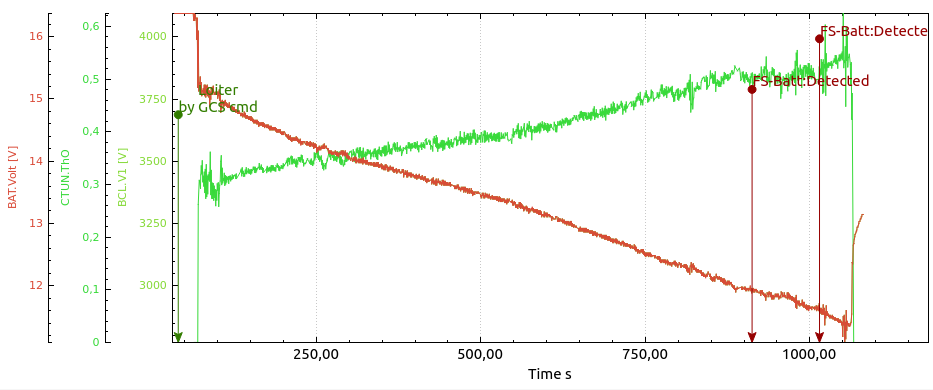
The predicted SoC percentage (blue) is clearly not perfect (yet) it was good at the end, not at the beginning, but that is not a problem, as it is easy to change by modifying the table.

Notice that it can still climb at as low as 10.5v , not exceeding 70% of throttle.

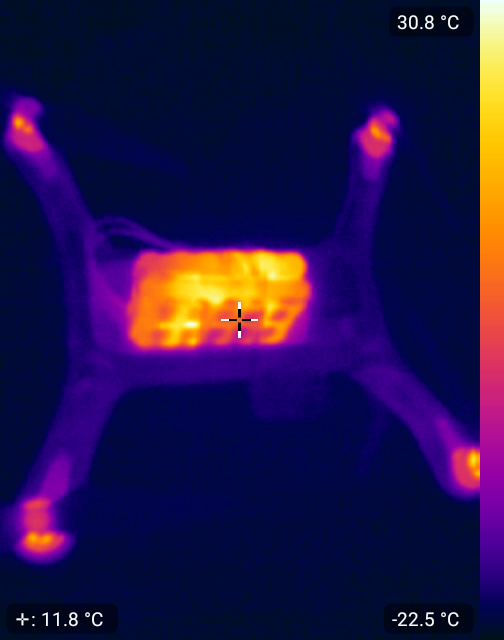
Post-flight thermal image: (somewhat affected by some kapton tape on the battery pack.)

TODO / Future:

Given enough interest, I plan to make a fully standalone BMS that can be user-customized to any chemistry, (min/max voltages) and so on.
With balancing, real current sensing, fuel gauge etc.

Tesla Snapon Jack Pad

Snapon Jack pad.

There are many photos showing of damage around lifting points due to misaligned, or missing jack pads.
Tire shops are very sloppy about it. And to make your average garage jack lift it correctly, requires fine placement.

The Solution:

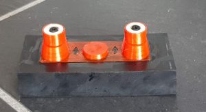
My jackpad, is made using 3cm high quality , industrial rubber sheet from Dunlop.
Then I  add an Thermoplastic polyurethane part, that makes sure it can only fit one way,(the correct way) to the jack pad.
Finally, some strong neodymium magnets will hold it in place, while you place the garage jack under.

Simple, easy, convinient. 

Once you get familiar with it, and where the jackpoints are, you don’t really need to look under the vehicle. Just move it around till it snaps into the spot.
Now the garage jack can be placed roughly beneath, and will still lift the car exactly as supposed, not touching anything else.

Tesla-Proof:

The massive natural rubber will most likely last longer than the Tesla, the magnets/mount, however, could be destroyed. So it needed a clever, collapsible  design:

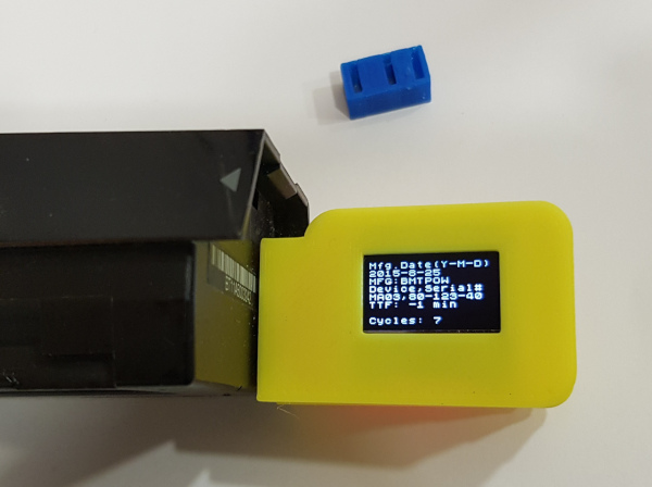
3DR Solo Battery diagnostic tool and charging adapter.

The blue thing in the photo is the shipping protection for the connector.

Image result for good news everyone

Related product:  https://madhacker.org/bmsone/

—–now back to what this page is all about:

This is the original Battery tool;

  • more information
  • more features
  • better understanding of the battery
  • firmware upgrades for all (and no incompatible versions)

Buy  boxed version ($35 +worldwide Shipping $4)

3DR Solo battery packs have lots of information that the average user will never see, they are also very nicely calibrated for voltage (cells and pack) as well as current.

Some of the information, like capacity, cell voltages, cycles, past low voltage condition, cell voltage difference, and manufacture date may be very useful.

Health data is very useful as well.

Below: two devices, one as delivered, the other with an XT60 connector for charging.

It’s easy to solder on XT60, charger cables, or other connectors right on the main connector. The XT60 is there just for illustration purposes, it’s easy to solder on most of the typical connectors (XT60, EC3) directly, the rest can be soldered on with wires.

“Hard” edition means it comes in a nice case designed by Purplemon on Thingiverse:https://www.thingiverse.com/thing:2841916

The device is not doing any calculations on it’s own, data is read from the battery, and presented.

Values and information details:

Pack Voltage
Charge level in %
Remaining capacity
Internal temperature.
Charging current. (Negative value indicate discharging current)

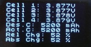
Cell voltages for cell 1…4 – should be self-explaining, any healthy pack will have very similar voltages after a flight.
Design capacity is what the pack was designed to be.
Actual capacity is shows the actual capacity as the pack ages.
Relative charge level is based on actual capacity of the pack.
Absolute charge level is based on design capacity of the pack.

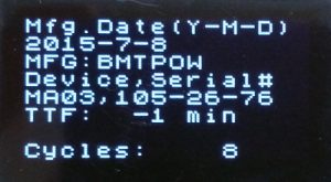
Manufacturing date in Y-M-D format.
Made by BMTPOW
The device name is MA03, serial number follows (not the same as the barcode on the pack)
TTF: Time To Full, if not charging, will display “-1”
Cycles: how many times have this pack been used. This is increased when discharged_capacity_since_last_increase > design_capacity.

The status word is bitmapped at least two bits we know are used, one indicating charging/discharging, the other tell if the factory calibration data is OK.

Should factory calibration data ever be corrupted, then you can never know if a reported voltage/current (used for capacity calculation !) is correct, and it’s dangerous to fly with such a pack. A very clear warning will be displayed.

Firmware >=1.5  say “Initialized” when BMS is calibrated&configured properly, or “NOT” initialized” if not.

There is also a warning for internal resistance deviation.
There is a “Cell Change” warning, I do not know what can cause it, or what exactly it means – both warnings above are for illustration purposes, I have no packs with such condition.

Status is expected to be 128(charging) or 192(discharging)  , 16608 is a fully charged battery. (Thanks to Bob that found that).

Since firmware 1.5, status understanding is much better, and most data is presented as text.

Health is 18 for all good packs (I do not have one that is bad) , but there are 16bit of data that can indicate quite a lot…

I’ll update this page based on user reports.

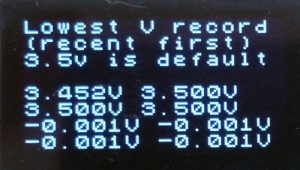
Lowest voltage record.
– Displays eight last low voltage records, some values are initialized as 3.5v, but it is the lowest values that indicate if the battery has ever been close to deep-discharge.

If the battery pack is connected, but not charging – after 180seconds, the DONE message will show, two minutes later the battery will switch off.
(Shutdown feature is inhibited at any time by pressing battery button to toggle screen.)

Serial output:

This dataset is being outputted to FTDI interface at 115200baud, one at 1hz.
The device will not go to sleep once you used the battery button to select an screen.

This allows for nice graphing of charging/discharging, and full monitoring using DataExplorer with the plugin I’ve made: Solo_Batt_Tool

Of course, you are free to do whatever logging you wish, the format is basically semicolon delimited, and temperature, cell voltages are multiplied with 100/1000 so you don’t need to parse thru commas.

The data format is:

$1;state(int);time(ms);voltage;current;rel_cap;abs_cap;rem_cap;temp_c;c1;c2;c3;c4;ser1;ser2;ser3;ttf;cycles;checksum(LF)

example:

$1 ;1 ;20988; 1550; 0; 52; 52;2724;2445;3874;3874;3875;3876;105;26;76;-1;8;0

How-To:

Plug into battery , switch on battery.
or:
Plug into battery , and provide charging current.  You can use any standard charger, select Li-Po 4cell program with no balancing (the battery have internal balancing circuit)

Firmware upgrade:

There is an custom bootloader on the device, so when I figure out more about the battery, it’s possibly to upgrade it using a standard FTDI cable and the avrdude tool (for Linux,Mac,Windows).

FTDI cable, with an extra pin header.

Insert pin header into FTDI cable, the protruding, short pins will fit into the SoloBatt_OLED’s six pins on the edge of the PCB.   You will need to cut away or puncture a little bit of shrink-wrap to access the edge.

The upper & lower of the six pins on PCB are marked BLK (black) and GRN(green)  – make sure that matches the orientation of the FTDI cable. (reversing does no damage)

Observe that there are two files in the firmware package:

“VG” is for displays with pin order: “VCC, GND, SCL, SDA” 
“GV” is for displays with pin order: “GND, VCC, SCK, SDA”

To write the new firmware you will need the avrdude application.

On Linux, it’s installed by:  “sudo apt install avrdude”

The firmware upload command is:

avrdude -patmega328p -carduino -P /dev/ttyUSB0 -b115200 -D -Uflash:w:SoloBatt_OLED.1.1.hex :i

/dev/ttyUSB0 is most likely correct, the number will be higher if you have more than one USB serial device

If you are using windows, replace /dev/ttyUSBx with COMx  , also, in windows, you’ll need some FTDI drivers.

Please note that the programming protocol is Arduino compatible just enough to make it work with avrdude, but it’s not really Arduino.

Firmware 1.1

  • Longer auto-off delay (was 2min , now 4min)
  • Longer time per screen 3s->6s
  • Serial output using FTDI cable at 115200 baud

Firmware 1.2

  • Warning if the battery has detected uneven internal resistance.
  • Warning named “change cell” (not sure when that is supposed to kick in)
  • Low voltage records.
  • Three digits in cell voltages.
  • Fahrenheit & Celsius temperature.

Firmware 1.3

  • Serial logging for Dataexplorer plugin (and any other data collection).
  • Shorter splash screen timeout.
  • Cosmetic fix for long status numbers on OLED display.
  • manual page flip. lets user skip forward to a certain page, and stops automatic rotation.  (connect a momentary switch between pin8 and pin9 – or – if you are using a microcontroller , just pull pin9 low.)

Download: SoloBatt_OLED_v1.3

Firmware 1.4

  • Pressing the power button on the Solo battery jumps to next screen, pressing button loads next screen, and disables the default time-based change. (you can watch one as long you want).
  • Manual page change disables auto-off.
  • Displayed data is updated at 0.5Hz

Download: SoloBatt_OLED.1.4

Firmware 1.5

  • Found out more about battery status, and presenting it as text. , among others, you may see “Fully Charged”, “Fully Discharged”, “Charging”, “Discharging”, “Initialized” “NOT initialized”, “Term.Disch.Alarm” and “Terminate Charge”
  • The old status “Calibrated” is now replaced by “Initialized”   – which means not only that the voltage/current sensors are calibrated, but also that the BMS is configured for proper operating limits and parameters.  A “NOT initialized” battery means improperly set/default BMS configuration.

Download: SoloBatt_OLED.1.5

Firmware 1.6

  • Moved the splash screen to back, now you see voltage & SoC om the first screen, no unnecessary delay.
  • Faster startup.
  • More (odd) errors are reported as text,  most error codes & bits are known. 
  • Cosmetic fixes. 

Firmware 1.7

  • Cosmetic fixes
  • No shutdown while current >0.1A

Sony QX1 Focus/Trigger control and feedback for drone use.

 RC, PWM control for QX1.

Buy QX1 modification service ($150)

Buy a QX1 battery eliminator 4.75V-23V

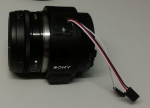
Sony ILCE-QX1 has great specifications at low weight, which makes it good for UAV photogrammetry use.  It can be configured using WiFi , then retain the configuration. (so it’s not necessary to even enable wifi for each operation.

About the modification:

The pop-up flash assembly is removed, an microcontroller replaces the flash assembly, it’s interfacing the motherboard indirectly, via FPC. The flash cover is slightly cut to make space for the servo (PWM input)   and logic level output that indicates shutter operation.

Can reliably do manual-focus shoot every 700ms. (no drops)

The camera will continue to function normally as before when the PWM interface is not supplied with power, except for the flash.

The modification requires micro-soldering; most narrow are three points within 1mm distance. Naturally, it voids camera warranty. (so test camera well before getting it modified.)

Features of the modification:

  • Camera will not shut down when inactive..
  • 3-wire servo connector (PWM input)
  • 1-wire logic output (high on shutter) -allows precise GPS positioning of each photo, and confirmation to the AP that photo is taken.
  • Command “Shoot” (just trigger a photo, for preset/manual focus)
  • Command “autofocus for 500ms, then shoot”
  • Command “autofocus for 1s, then shoot”

Suggested ArduPilot setup:
CAM_DURATION = 1
CAM_FEEDBACK_PIN (set to correct input)
CAM_FEEDBACK_POL = 1
CAM_MIN_INTERVAL = 300
CAM_SERVO_ON = 1200
CAM_SERVO_OFF = 1500
CAM_TRIGG_TYPE = 0

PWM Commands:

990us … 1400us = Shoot instantly (manual focus)
1401us … 1600us = Idle
1601us … 1800us = autofocus 0.5s , shoot
1801us … 2200us =autofocus 1s , shoot

I can convert your camera, but I am unable to provide QX1 cameras from Norway.

Contact for more information.

Mavlink to HoTT adapter – telemetry to Graupner HoTT, and LED control


13 May 2018: Firmware Ver 1.9 is out ! , see below.   🙂

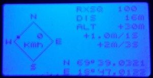
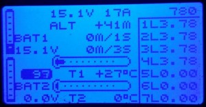
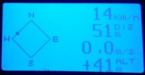
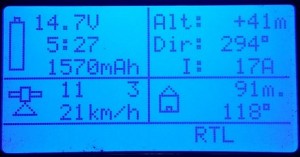
ArduPlane , ArduCopter (and similar Ardupilot projects) use Mavlink for telemetry, while Graupner has a very useful telemetry system HoTT.
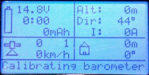
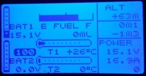
This device provides all the data Graupner’s EAM(Electric Air Module),GAM(General Air Module),GPS,Vario modules offer.

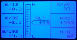
Data that Ardupilot does not provide in it’s telemetry stream: (distance and direction to home, 1s,3s,10s vario-data and battery cell voltage/min/max voltage) are calculated in the device.

ArduCopter and ArduPlane are detected automatically, and correct mode-names will be displayed.

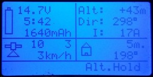
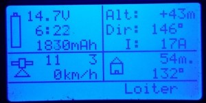
The GPS position format is converted from DD (degrees,decimals) transported by mavlink, to the DM (degrees, minutes.decimals) as expected by HoTT, direction and distance to home is also calculated, (it’s not provided by AP).

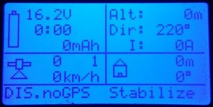
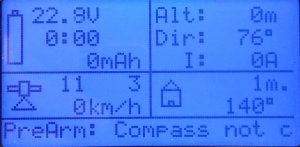
Note the “DIS.noGPS …” = Disarmed, no GPS Fix, mode is Stabilize.

20150310_194526

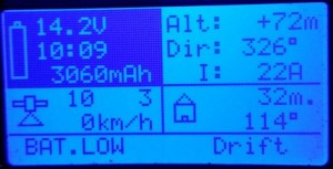
This is the inverting/flashing voltage background, (also audible warning) for  “Battery Low”.

20150310_195643

Arduplane & Arducopter modes are visible as text.  Future/unknown modes as number.
20150310_194732 20150310_19475620150310_194916 20150310_194940 20150310_195124 20150310_195201 20150310_19521620150310_19525620150310_194847

Real status messages:

The device enables HoTT to display actual Ardupilot system messages, longer messages are split and displayed as two interchanging parts. like this:

DSC_0005    DSC_0004

Bootup messages:

_20160425_225845

Should a prearm check, or arming check prevent you from arming, you will know exactly what the problem is.

DSC_0015   DSC_0011

For a quick overview over all messages you may see, here is a dump of messages found in ardupilot source code

This method is superior to FrSky telemetry, which at best, tries to recognize, and encode the messages, then a .lua script in the transmitter is supposed to display a corresponding/equivalent message.  That method works only for known messages (depending on firmware), and things can get “lost in translation”.

This device, however, just display text as-is, and thus can display new and future messages as well as composite messages that may contain variables or debugging info.

Firmware upgrade:

There is an custom bootloader on the device, it’s possibly to upgrade it using a standard FTDI cable and the avrdude tool (exists for Linux,Mac,Windows & more).

FTDI cable, with extra pin header.


Insert pin header into FTDI cable, the protruding, short pins will fit into the Mav->Hotts  six pins on the edge of the PCB.

The upper & lower  of the six pins on PCB, are marked BLK (black) and GRN(green)  – make sure that matches the orientation of the FTDI cable. (reversing does no damage)

To write the new firmware you will  need avrdude application.

On Linux, it’s installed by:  “sudo apt install avrdude”

The firmware upload command is:

avrdude -patmega328p -carduino -P /dev/ttyUSB0 -b115200 -D -Uflash:w:Mav2Hott.v1.9.hex :i

/dev/ttyUSB0 is most likely correct, the number will be higher if you have more than one USB serial device

If you are using windows, replace /dev/ttyUSBx with COMx  , also, in windows you’ll need some FTDI drivers.

Please note that the programming protocol is arduino compatible just enough to make it work with avrdude, but it’s not really arduino.


Firmware 1.6

  • Audio warnings for mav_severity >2 only (now that severity is fixed)

    Firmware 1.7

  • Fixed and expanded low/critical battery threshold

Firmware 1.8

  • Relaxed audible warnings

Download: Mav2HoTTv1.8

Firmware 1.9

  • Updated flight modes for ArduPlane & ArduCopter to include modes from current master (next release) of those.

Download: Mav2HoTTv1.9


Low battery and critical battery alarms;


  • 3s  Warning 10.8v , Critical  10.2v
  • 4s  Warning 14.2v , Critical  13.6v
  • 5s  Warning 18.0v , Critical  17.0v
  • 6s  Warning 21.5v , Critical  20.4v

Warning inverts/flashes the part of the display that contains battery information, and give relaxed audible warning.  The LEDs, if connected, are blinking diagonally (only warning/critical state does that)

Critical battery level does the same, but the audible warning is more intense, and rapid,  LEDs are flashing diagonally very fast.

Detected cell count can be seen as number of displayed cell-voltages (which is calculated from initial battery voltage)

20150310_195643

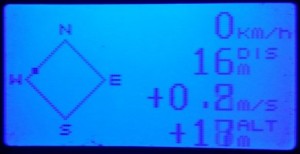
most useful information at a glance, by using just heading, and flying so it gets equal to gearing to home – you can fly home even without seeing the model.

Mavlink mode-controlled LED controller.

There is no need for HoTT telemetry to be sent, only read the Mavlink protocol input, for the LED controller to work.

For ArduCopter, there are four outputs for leds/strips (non-amplified, so you will need a transistor if you wish to use them with more than a few LED’s)

The blinking patterns are different for each mode, but follow this system:

  • Stabilize = solid on
  • Alt-hold = short off-time on rear leds
  • Autopilot modes does not have solid front light, indicating that AP is on
  • Diagonal blinking patterns are used for errors, noGPS fix, low battery, and anything else that may be reported over 3DR radio/mavlink as an critical state.
  • Warning/Critical blinking ignores LED Switch function.

The outputs are on pin 7(RearLeft),8(RearRight),9(FrontRight),10(FrontLeft)  .   – they will flash diagonally in case of critical events, and different patterns depending on mode/situation , GPS fix and so on.

LED Switch function: if pin2 gets a PWM betwen 900…1200µs , the LEDS goes dark except if critical condition, or a battery warning – in case of which, the PWM will be ignored, and LEDs will flash anyway.

Safety:

The device does only read mavlink, (it’s connected to telemetry TX pin) , fed with power from receiver or telemetry port,  and so it is unable to influence the operation of the autopilot in any way.

Connecting:

  • Voltage: GND and +5v goes to Pixhawk/APM or Receiver.
  • Connect RX pin to your 57600 baud telemetry TX pin on Pixhawk/APM
  • Connect Pad5 to your HoTT receiver’s telemetry input.

If you wish to power it from Pixhawk, It’s ok. This would be the connections then:

  1. Telemetry connector(of your choice),  Pin1 (red wire) – goes to VCC on the device
  2. Telemetry connector Pin2 goes to device’s RX pin
  3. Telemetry connector Pin6 (last one) foes to device’s GND
  4. Pad5 on the device, is connected to you HoTT RX’s “T” input.

This is an example of a possible connection:  Usually, people connect it in paralell to another Mavlink device, like OSD or radio, so there is no need to purchase a DF13 connector.

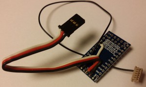
note that the device comes without wires, I assume most people do have a old servo cable, and are better off installing the length actually needed.

MavHottAdapter

 Troubleshooting:

  • If HoTT display (in the  mode that display text) says NO MAVLINK … check mavlink
  • If you only see mode, no other info –  check the parameters below, used to tell Ardupilot how often to send the different messages as suggested below:
  • SRx_EXT_STAT = 2 ; 2Hz battery voltage, current and capacity GPS,fix .RAW GPS position, velocity, altitude
    SRx_RAW_SENS = 2 ; gives 2Hz pressure, and temperature.
    SRx_POSITION =2 ; position mixed with accelerometer & barometer data
    SRx_EXTRA2=2 ; heading, baro altitude, climb/descent rate
    SERIALx_PROTOCOL = 1 ; set the serial/telemetry port to Mavlink protocol

Buy Mavlink>HoTT interface ($60)
Shipping :

(Cart will appear below)


PWM>FLIR: Control FLIR TAU, TAU2, Quark using PWM (RC Radio)


A quick demo, switching between 8 modes using a servo-tester. The TAU640 in this video is set for outdoor use, and does not show the full advantage of Ice&Fire modes inside.


What you get:

  • A microcontroller on a small PCB (18x33x3mm) with soldering pads. Preprogrammed with 8 different modes as in this video, or up to 10 custom modes (as ordered).
  • The circuit works on 5v, uses less than 10mA.  You can connect it using 3 wires,  just like a servo)
  • The modes are selected using a knob on your transmitter, PWM decide mode, just like a servo position.
  • Serial data, is sent from the device to your FLIR device using one wire – (assuming you have common ground)
  • The common modes in this test video shows 8 modes I’ve found very useful.

What you need:

  • FLIR TAU ,TAU2, or QUARK thermal core.
  • For TAU,  “Wearsaver” helps a lot.  – It offers big soldering pads for connecting to the Hirose 50p connector. RX(pin2)
  • For Quark , you need to connect the serial signal to pin 15 of the Samtec 60 pin – connector. or to the breakout board, if you that.

Connection instructions:

Connect PWM (white wire) from your receiver to pad9 on PWM>FLIR device
Connect “-” (black wire) from your receiver to GND on the PWM>FLIR device
Connect “+” (red wire) from your receiver to VCC on the PWM>FLIR device

Connect pad8 on the device to your RX pad on wear saver, thats solder pad with green ring in the picture below.
Connect ground and +5v to TAU (black and red pads in picture below)

Finally, for information only:composite video out is on the yellow pad, and video ground on the blue pad on the TAU wearsaver.

TAU Wearsaver connection

Default mode configuration is:

1, white hot, no zoom , spatial threshold gain 34d.
2 white hot, 2x zoom, spatial threshold gain 34d.
3 Black Hot, no zoom , spatial threshold gain 34d.
4 Black Hot, 2x zoom, Spatial threshold = 9d
5 Fusion,no zoom, spatial threshold gain 34d.
6 ICE & Fire, no zoom, spatial threshold gain 34d.
7 Rainbow, no zoom, Spatial threshold, Gain = 34d
8 ICE & Fire, no zoom , Spatial threshold 17d

You can output a PWM from an autopilot, controlled by GCS, having any GUI you prefer.  – Or , if  you are will be controlling the PWM directly from a RC radio, you  do not need a rotary knob with steps, it’s perfectly easy to hit desired mode even with smooth knob due to the quick visual change, and equal “distance” between modes.

Buy PWM>FLIR interface ($160)

(Cart will appear below)

CryptoTelemetry – Secure firmware to prevent drone hijacking.

The CryptoTelemetry firmware:

Due to the proven vulnerability of current telemetry modules, I’ve developed something significantly stronger.

The source is not open, because it’s not real strong, certificate-based encryption, that allows end-user to replace, create new certificates. One advantage of doing it this way, is that you can purchase more radios and add them without having to reprogram all.

The secrets are permanently stored inside, and opening the source would give glues of possible attack vectors.  I intended this to be a long time viable, secure solution.

Still – the owner have the option to get more radios that will work with his private network.

Features:

  • 433,470,863,915Mhz support.
  • Fully compatible with all ground station configuration tools.  All the common AT commands and parameters are there, there’s even a NetID that will let you make different networks within your encrypted network – should you wish.  Example, if you have 4 CryptoTelemetry radios,  you can have 3 in different UAV’s , all have the same network ID, and will speak to the same GCS, typical use is “one at a time”. Or you can set two radios with NetID different than the others, and use two GCS and two UAV simultaneously. – Note that no non-CryptoTelemetry radios will be able to communicate with these radios.
  • Locked down firmware, even if one malicious customer purchased it for analysis, it would be hard to learn anything from it.  – Then it would take some time to find your encryption key.
  • Personal encryption key.  (most tend to be 11digits) Only the customer will have the key, it is NOT stored here. To order more radios for the same network, it’s essential to provide the key so a properly encrypted firmware for your radio can be generated.
  • Your radios will operate in your network, no one else will be able to see the data, or encrypt without some extensive cryptanalysis and hacking.
  • Encryption can be disabled by disabling ECC – radios enter then a transparent mode, which is 2x the usual ECC data rate.
  • Efficient; the data rate is the the same as ECC,  (half of the non-ECC speed.)
  • ECC (Golay24) is still active, for every 12bit , up to 3 bit errors can be corrected.
  • Delivered on standard, authentic, genuine 3DR telemetry radios.
  • If customer provides radios, it can be flashed onto a several other/compatible radios.
  • Reversible – should this method be obsolete one day, it is fully possible to convert these radios to run official 3DR provided firmware.

I am using this firmware for all my commercial operations as well as hobby flights, it is well tested.

Get your radio reprogrammed with CryptoTelemetry ($85):

Buy new original 3DR Radio with CryptoTelemetry ($135):