Worlds most advanced paintball marker controller. (back in’97)
New electronics for Brass Eagle’s Rainmaker
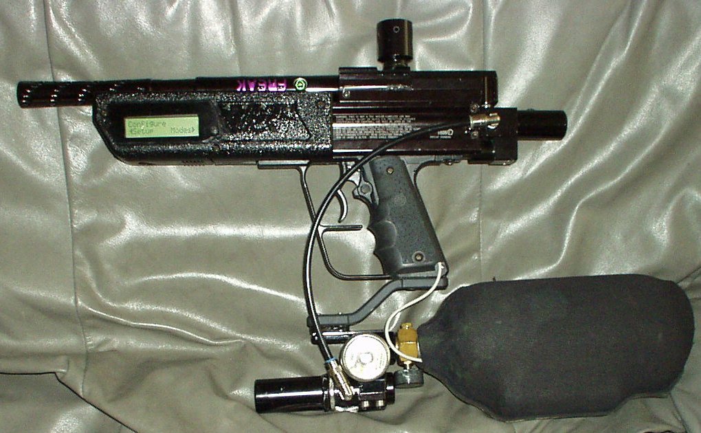
-who says the standard Rainmaker must be ugly-grey – here it is in black(picture taken with flash)
(I do not sell them anymore – sorry)
This is what you get :
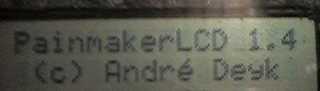
-PainmakerLCD board
-Better trigger switch , (much tighter)
-The optocoupler if you want to use the Revolution-Starter option
-Schematics you might need.
-Shipping to anywhere on Earth
Those were sold for US$ 230.
Some facts :
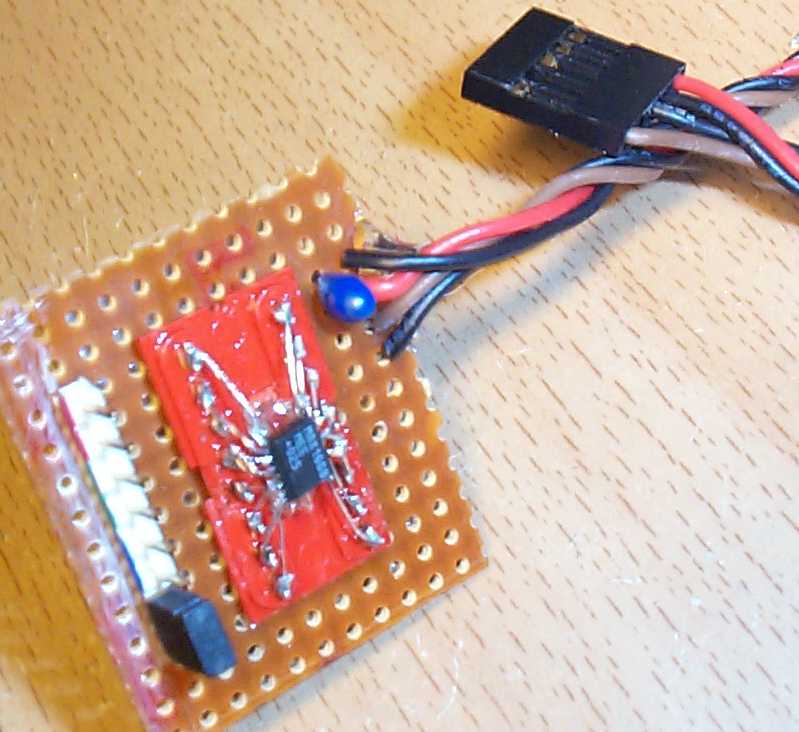
- – all electronics are inside the fore-grip , on two dual-sided PCB’s with a “bus” in-between
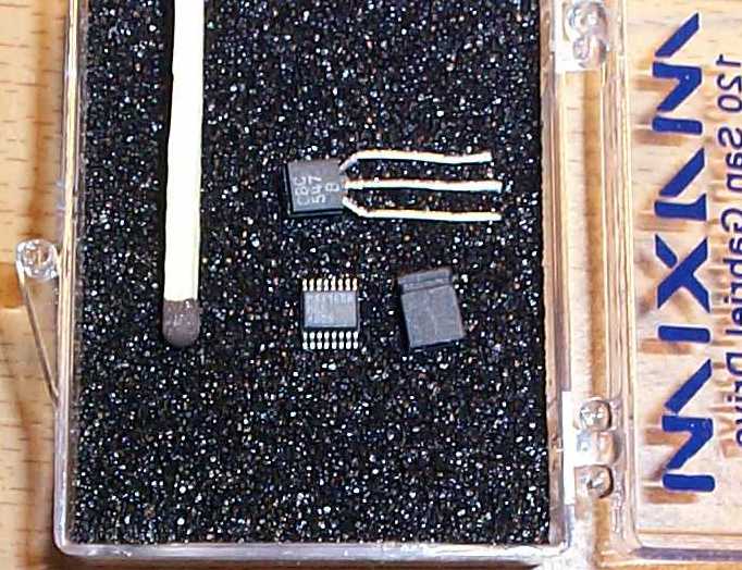
- – CPU is a 20Mhz RISC processor , with 8KB Flash EEPROM .
- – The Source code (ver 1.0) were 3328 lines of pure assembly. (takes 48 A4 pages when printed)
- – All settings / preferences are saved in EEPROM ,… no battery is needed to keep settings.
- – All menus / functions are controlled by only three buttons .
- – Electronic Safety is on when in any configuration menu. or reloading (loader lid open)
- – It’s powered by one 9V Ni-Mh battery inside the grip , but can also take 12Volts or more.
- – It have both a high-intensity LED and high-frequency beep (hard to localize the sound , HF sound does not travel as far as lower freq. do) , beeping is used for warnings/alarms/ button-confirmation + +
Features & Menus:
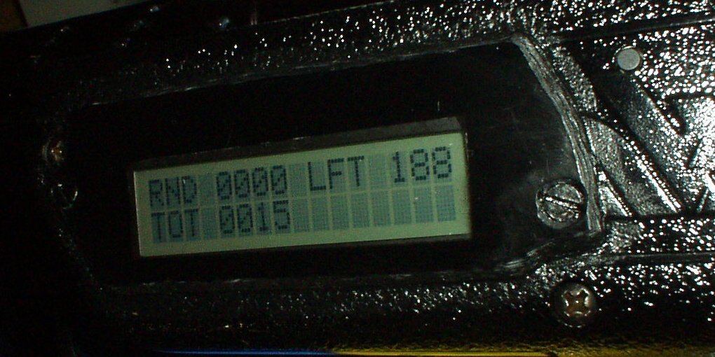
It all starts with Intro …
(Ready For Action: Totally fired 0015 , this round 0000 , LFT(left in loader 188 balls))
(This is the playing screen)
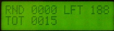 This is how the LCD looks like during a game. There are two independent counters that can be reset when you like , and can be saved to EEPROM and loaded at next game.
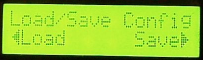
Load/Save Configuration , Painmaker LCD loads all previously saved settings at each boot, if you then make any changes they will not be saved until you save them , on the other hand , you can make some changes you are not happy with , and just load the previous (takes only two button-presses to do that.)
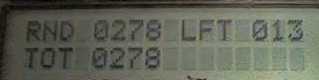
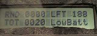
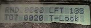
(After 278 balls are fired the last round (since last RND reset), totally 278 this “day” (since last TOT reset) , and there is 13 left in loader) so the LED is lit as a warning (because warning is on (in this case) if there are <=25balls left)
(This is the playing screen)
 This is ho
w the LCD looks like during a game
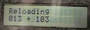
The loader detected that the loader lid is open ,(reloading) the display is showing this , until the loader is closed , safety is on. , the LED is turned off.
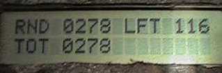
Loader is closed , the result of the above calculation (balls left + balls in a pouch) is 116. (This is the playing screen)
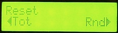
Reset menu : allows to reset total counter , and/or round counter “-” is left button “+” is right button
Menu : Battery – Shows battery voltage ,+/- 0.01 volt ,( it’s calibrated with a Fluke.)
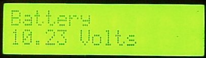 this is updated so fast , that voltage changes are “animated” on the LCD (when 46 changes to 45 both “6” and “5” are showing because the 10bit DAC cannot decide the LSB
  very cool.
Low Battery Warning Menu : … user can decide when the low-battery warning (audio) should be activated, (the minimum working voltage is different for Ni-Mh , Ni-Cd & Alkaline batteries. (+/- buttons increase/decrease this value , holding down “+” increases value fast , holding down “-” decreases value fast)
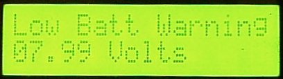 a “beep” sounds every idle 2 sec if voltage is low
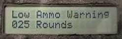
If the battery is low , It’s also on the main screen…
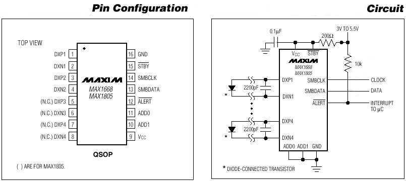
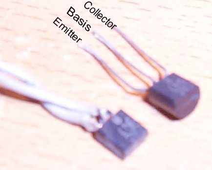
Temperature : a precalibrated to 0.5° C state-of-the-art IC is measuring the temperature , and sending the results serially to the CPU , It’s not like the “AngelLCD” thermometer , but a really professional (industrial) thermometer , calibrated to +/- 0,5°C . If you live in Norway (like me) and play when it’s about 10°C , it might be cool to know how cold it is , as the paint starts breaking really easy at that low temperatures . It might be useful at high temperatures too.
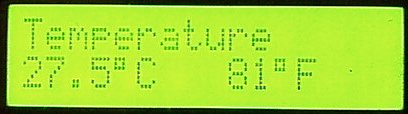 added Fahrenheit degrees , at first I wanted to calculate it , but it’s pretty difficult because of the decimals needed , , so I use a lookup-table , to save space the table have 60 entries , 1..60 °C , so the Centigrade has higher resolution (0.5deg) and the Fahrenheit temperature is the same for 25°C and 25.5°C.
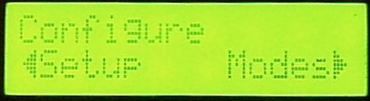
Configure menu is where settings like burst-size and loader capacity is set in “setup” part , and burst-on/off , fullauto and other are under “modes” , go to left or right to continue setup from here.
Loader capacity presets the maximum Loader capacity … (+/- buttons increase/decrease this value)
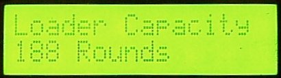 188 is the space in a Revolution + it’s neck.
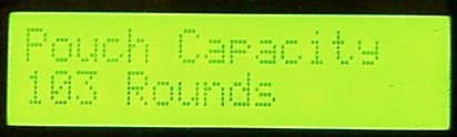
Pouch capacity must be known, (to add right amount of balls when loading) … (“+”/”-” buttons increase/decrease this value , holding down “+” increases value fast , holding down “-” decreases value fast)
Here is the low ammo warning configuration , it’s now set to warn me when 25 balls are left (“+”/”-” buttons increase/decrease this value , holding down “+” increases fast , holding down “-” decreases fast)
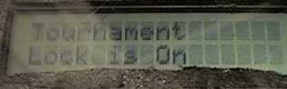
Tournament-Lock This menu will ONLY appear if the Tournament-Lock is ON and then NONE of the menus below will show. Causing the last selected configuration being used without any way to change it during game.
This is THE BEST Tournament-Lock feature because : It will let me not only lock-out the coolest features , (like any Tournament-Lock does) , but It allows to keep any settings , and only restrict changes. Like : I’m will play in a Scenario-Game (Command & Conquer) which allows any fire-mode up to 9bps , even fully automatic . So I can choose any mode I like , and still restrict myself from being able too choose 13bps . by selecting Tournament-Lock when rebooting , , and a battery-change does NOT affect the Lock’s state.
The only way to toggle this selection is to reboot , while holding all 3 menu-buttons (beeping) depressed in about 2 seconds (during the boot & intro sequence) which is , needless to say , not possible during the game. (playing with battery & beeping 2 seconds will catch referees attention.) m and the process would need to be undone at end of game.
the display also shows that Tournament-Lock is active during the game , (unless when that space is used to tell important things like Low-Battery) , anyway the first “Tournament Lock is On” can be reproduced.
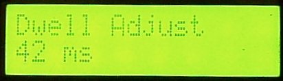
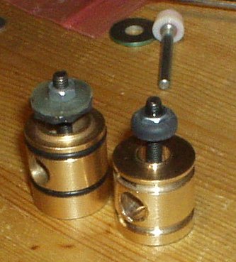
Dwell Adjust : 1…30 ms in 1ms steps .
 no rainmaker can shoot at speeds like 15bps ,because it will not have time enough to feed each ball , only the balls that quickly gets into place. this is because of the low pressure controlled ram needs a minimum of time to cycle the mechanism . and at higher rate-of-fire there is very little time to feed next ball. When this time is too long , time is wasted , precious time that could be used to feed ball… (any default configuration on any controller board waste some time) on the other hand , When this time is too short , The rainmaker will have a significant blowback , (because it’ll open the “chamber” when there is still very high pressure in the barrel) , of if this time is way-to-short , it will not fire at all , (the ram is reversed before it’s in hammer-release position)
So , this value should be set as low as possible , allowing normal function , this will extend the ball-loading-time. This setting does NOT influence the rate-of-fire in any way, each ms set here is compensated for.
The optimal value of this setting will vary from rainmaker to rainmaker , because the time delay needed is dependent on : low-pressure-spring , ram , and hammer spring.
Also , having the optimal setting will save battery , the 9volt battery works pretty hard when it opens the MAC valve. Because of the way PainmakerLCD is constructed it uses a higher voltage to control the Power-MOS-FET that opens the 6volt valve. This gives a impressive raise-time and very “strict” MAC-valve movement. , (anyway use Ni-Cd rechargeable battery)
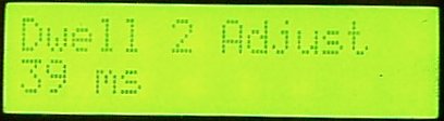 To make the adjustment easier to try out , There are 2 Dwell settings that can be programmed , and then toggled.
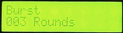
Configuration of “burst” or “family” mode (“+”/”-” buttons increase/decrease this value , holding down “+” increases fast , holding down “-” decreases fast)
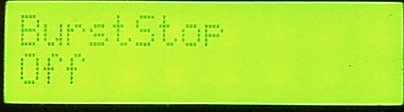
BurstStop = (On/Off) let’s user choose if a burst should be interrupted when trigger released , or not.
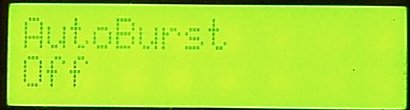
AutoBurst = (On/Off) , Similar to AutoRepeat , if on , burst repeats with a brief pause in between (until trigger released) , a three ball burst sounds like “bang-bang-bang….bang-bang-bang….bang-bang-bang….”
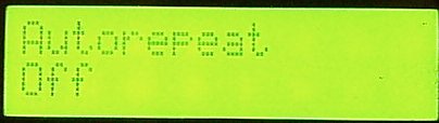
Autorepeat : whatever the fire mode is (normal/burst/turbo) , when trigger is held down 250ms (0.25sec) , the Painmaker switches to fully automatic until trigger is released , good for bad situations (and then returns to the mode it was in before) , (pressing “+” is “ON” , pressing “-” is “OFF”)
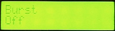
Burst: turns on/off the burst/family mode , which can be set to anything between 2 and 255 balls (pressing “+” is “ON” , pressing “-” is “OFF”)
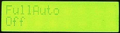
Fully-automatic : turns on/off the ammo-wasting mode. (pressing “+” is “ON” , pressing “-” is “OFF”)
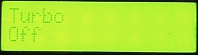
Turbo Mode menu : turns on/off the turbo mode. (pressing “+” is “ON” , pressing “-” is “OFF”)
Fire rate , applies to all fire-modes and can be programmed to anything between 6.5 and 15** balls/s in 0.5rounds/s increments (“+”/”-” buttons increase/decrease this value one step each click)) this setting limits the fire rate in ANY selected mode. It applies to all fire modes.
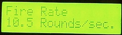
**There is no gravity-loader that will provide more than 13balls/second continuously (more than 4 shots), my tests gave me some “blanks” in between shots. There are many things that will set the maximum fire-rate you can achieve : Loader, Dwell -(shorter is better) ,Low-Pressure system’s pressure (a little higher pressure will move bolt faster) , Bolt , (heavy bolt will move slower) +.
I made the selection go to 15bps in 0.5bps steps to allow everybody experiment and find your own maximum setting , my calculations (of recorded audio form Rainmaker) makes me believe that 15bps is possible with forced feed or a longer vertical feed , (if the balls are “falling” faster into chamber there won’t be blanks) , 10 or 10.5 is the maximum of what my revolution loader can deliver continuously.
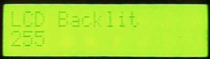
Backlit sets the intensity of the backlit when in menu mode , (backlit is always of in game mode) – 0 means off , 255 = max intensity
Those three menu-buttons (“+” , “Select” , “-“) and the mini-jack connector to the Revolution-Loader
Battery is now inside the grip
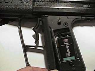 … but a higher-capacity battery is recommended for trouble free , long play , go see the “PainmakerLCD Power” page..
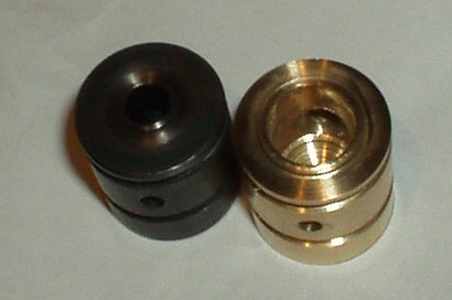
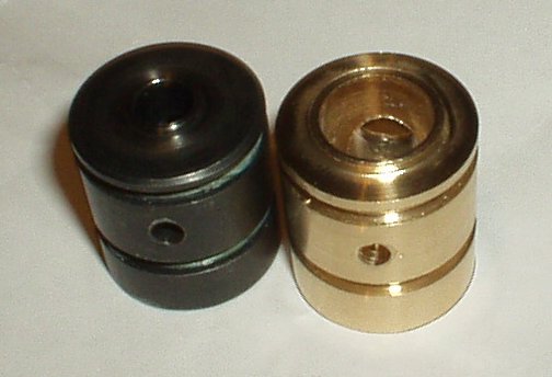
(Revolution-Loader mod.)
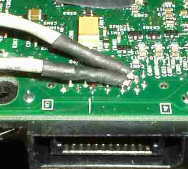
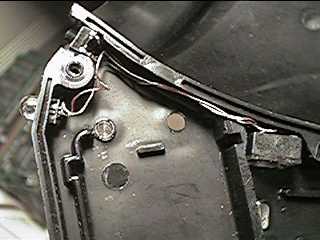 the button that detects when the lid is open , and the high-intensity-LED that’s used as a warning
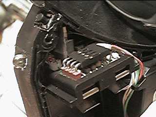 button & LED in place , and also the original Revolution-loader electronics.
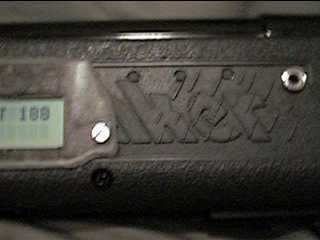
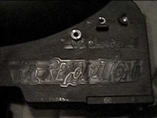 closed revolution-loader , with the mini-jack connector
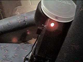 difficult to photograph , but it’s the high intensity almost LED blending the camera to tell the ammo is low
FAQ
- Q: Is it an ADD-ON or what ?
- A: It’s a complete replacement of ANY wires/electronics you might find inside your Rainmaker. or any compatible marker)
- Q: Can you make it fit inside gripframe ?
- A: ….technically yes , but not using the display I’ve programmed for (it’s too big) , I would also have to order some professional PCB’s made for SMD (SurfaceMountedDevice) components. the size is as it is, because I did built it to be technically perfect , like : the PowerMOSFET controlling the valve is totally isolated from the CPU , using a optocoupler. , all this stuff takes some space u know. , so…. It can fit inside , but will need a smaller display and a new PCB , ….today , only the earlier project , the Painmaker (noLCD) can fit inside .. it has much common functionality , fire-modes/autorepeat , on the other hand , a display inside grip us useless during play (may have little information and take some time too read) , while when using this big LCD you can read it all very quickly by only turning the marker.
- Q: Is it only for Rainmaker or will it fit any marker.?
- A: It will work on ANY marker , the trigger input can handle both optical (semiconductor)) and mechanical-switch triggers , and the Valve/Solenoid output is very powerful , and can handle whatever load you need , the PowerMOSFET is driven by a higher voltage than it switches , it means the MOSFET is switching really FAST and powerful (very low internal resistance and low rise-time) NO other controller boards for any paintgun does this , as it requires a higher voltage than the CPU works at and thus a electrical isolation between PowerMOSFET and CPU … The whole thing needs power supply between 7…24Volts.
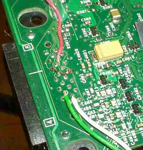
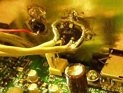
 This is the inside of XBOX’s rear shielding plate.,

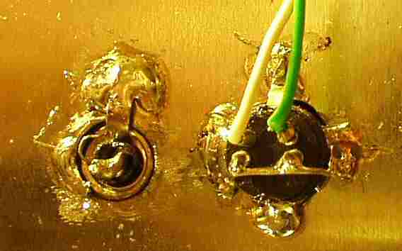
 I made two different .,,,
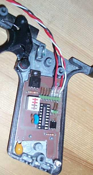
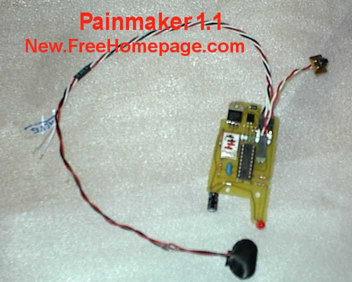
 table 2 (off,off,off,off) is default.
 table 3 (setting 3 is default)
 table 4 (setting 13 is default)
 table 5 (setting 3 is default)