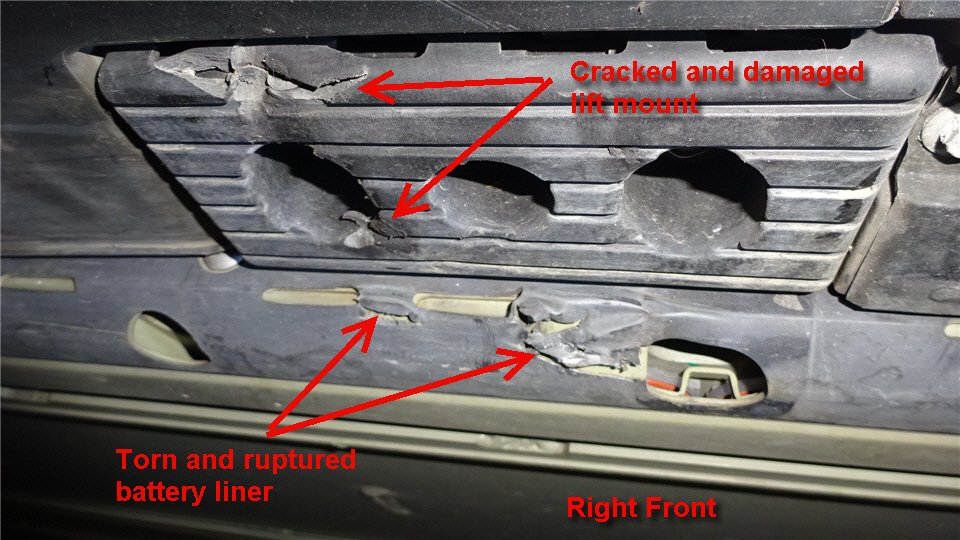
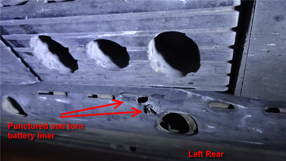
There are many photos showing of damage around lifting points due to misaligned, or missing jack pads.
Tire shops are very sloppy about it. And to make your average garage jack lift it correctly, requires fine placement.
The Solution:
My jackpad, is made using 3cm high quality , industrial rubber sheet from Dunlop.
Then I add an Thermoplastic polyurethane part, that makes sure it can only fit one way,(the correct way) to the jack pad.
Finally, some strong neodymium magnets will hold it in place, while you place the garage jack under.
Simple, easy, convinient.
Once you get familiar with it, and where the jackpoints are, you don’t really need to look under the vehicle. Just move it around till it snaps into the spot.
Now the garage jack can be placed roughly beneath, and will still lift the car exactly as supposed, not touching anything else.
Tesla-Proof:
The massive natural rubber will most likely last longer than the Tesla, the magnets/mount, however, could be destroyed. So it needed a clever, collapsible design:
Update: As of Arducopter 4.0.0 for Solo, the motor slew rate is available, and this mod is NOT required if you are happy to use slew rate.( which gives a little less responsive copter, lust like the original 3DR fix.)
3DR Solo Cube (Pixhawk 2.0) outputs 3.3v PWM, the IO buffers run off 3.3v on both sides, while they are perfectly capable of delivering 5v. Using 5v is safer when using 3DR Solo firmware with PWM slew rate, and required for ArduCopter code on Solo.
The simple solution is to purchase “Green cube” (usually sold out) or modify Pixhawk 2.1
The alternative solution, is to modify Solo’s Pixhawk 2.0 Cube.
This does require some soldering skills, and can be done by any semi-decent repair shop if you cannot do it yourself.
(The width of the buffer chip is 4.5mm)
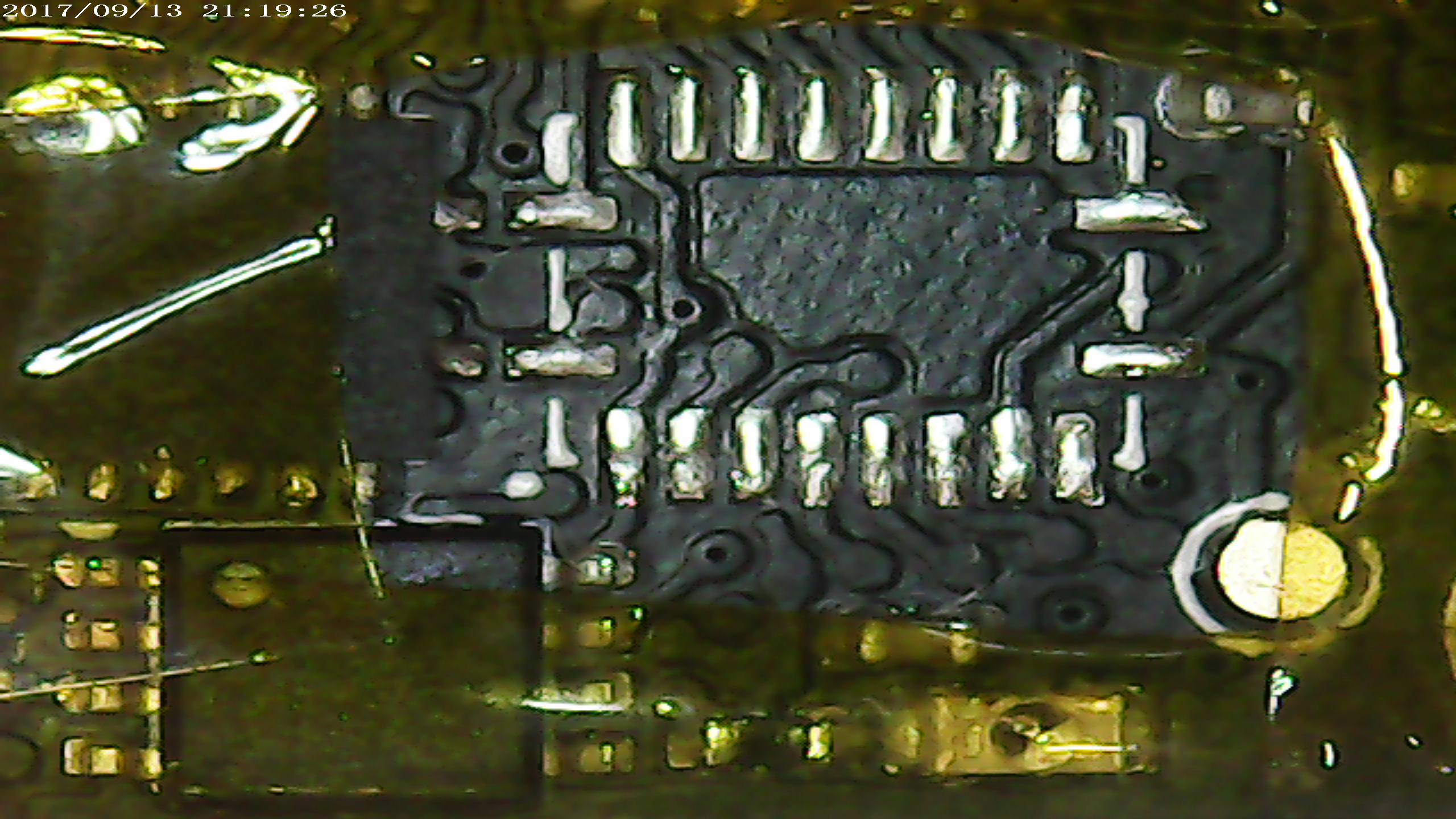
The two first images show two different PCB layouts of the Pixhawk 2.0 cube, so everybody should recognize, and stick to one 🙂
Open the cube, and locate the rightmost buffer ic. (TXS0108E marked YF08E)
Desolder the buffer (here seen on another PCB layout):
Cut the trace that feeds the upper left pad:
Re-solder the buffer:
Attach a thin wire to the pin. (provide 5v to the buffer’s VccB)
The other end of wires are routed to the clearly labelled 5v pad in the upper right corner of the Pixhawk2.0 :
Finally, clean and cover wire using conformal coating, to prevent vibrations to damage it: (UV inspection below)
Congratulations, output 1…8 output is now 5v.
Final note: the UV inspection picture picture shows another buffer, not used for PWM, the photos are taken on different occasions, and while batch processing many, not only one, so the time is not 30minutes between desolder and resoldering one device as timestamp may suggest.
Should you use a professional to do this job, it should take <15 minutes.
Modified files for uploading using Solex (Just copy into /Solex/download/package) – The only modification is to make Solex ignore the fact that the modified cube still runs the old 3DR fork of ArduCopter.
Once you upgrade to the 3.5.2 I provided here, you can continue to upgrade to newer versions using SSH /Solex and/or OpenSolo as if you had the greeen cube.
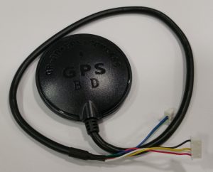
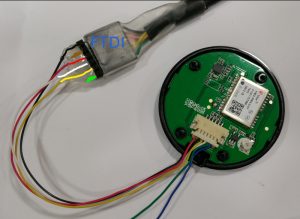
3DR Solo GPS upgrade to uBlox M8N – the cheap’n’simple ($15) way:
Be sure to buy a GPS that looks like this:
several sellers on Ebay sell them for less than US$15 including shipping from China.
4 Screws later, inside, strip the wire, and interface with a standard FTDI cable for configuration:
Using uBlox u-Center
Yes, it’s windows-only, that sucks, but it runs just fine in Wine , just make a link to the serial device like:
sudo ln -s /dev/ttyUSB0 ~/.wine/dosdevices/com5
configure NAV5 like this:
remember to store to flash:
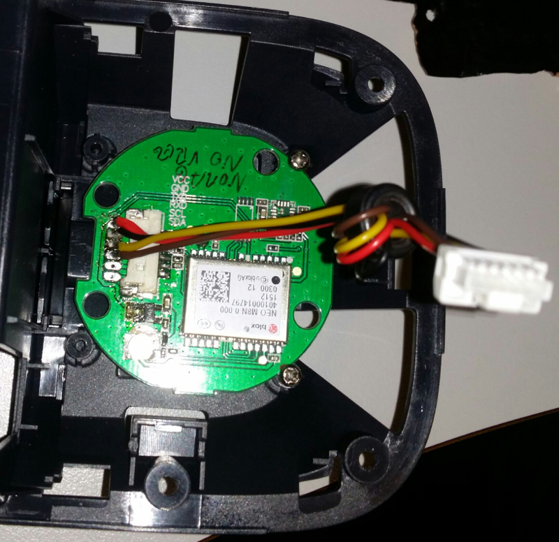
Remove Solo’s GPS module, by making two small grooves in the pcb where the two screw-holes are, the PCB if held in place by the two original screws.
Cut off one of the connectors, and solder the wires to the pads:
Red=VCC
Black=GND
Yellow to TX
Brown to RX
3DR Solo battery packs have lots of information that the average user will never see, they are also very nicely calibrated for voltage (cells and pack) as well as current.
Some of the information, like capacity, cell voltages, cycles, past low voltage condition, cell voltage difference, and manufacture date may be very useful.
Health data is very useful as well.
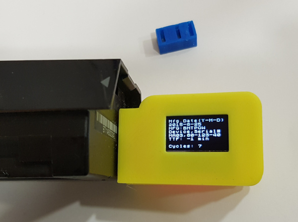
Below: two devices, one as delivered, the other with an XT60 connector for charging.
It’s easy to solder on XT60, charger cables, or other connectors right on the main connector. The XT60 is there just for illustration purposes, it’s easy to solder on most of the typical connectors (XT60, EC3) directly, the rest can be soldered on with wires.
“Hard” edition means it comes in a nice case designed by Purplemon on Thingiverse:https://www.thingiverse.com/thing:2841916
The device is not doing any calculations on it’s own, data is read from the battery, and presented.
Values and information details:
Pack Voltage Charge level in % Remaining capacity Internal temperature. Charging current. (Negative value indicate discharging current)
Cell voltages for cell 1…4 – should be self-explaining, any healthy pack will have very similar voltages after a flight. Design capacity is what the pack was designed to be. Actual capacity is shows the actual capacity as the pack ages. Relative charge level is based on actual capacity of the pack. Absolute charge level is based on design capacity of the pack.
Manufacturing date in Y-M-D format. Made by BMTPOW The device name is MA03, serial number follows (not the same as the barcode on the pack) TTF: Time To Full, if not charging, will display “-1” Cycles: how many times have this pack been used. This is increased when discharged_capacity_since_last_increase > design_capacity.
The status word is bitmapped at least two bits we know are used, one indicating charging/discharging, the other tell if the factory calibration data is OK.
Should factory calibration data ever be corrupted, then you can never know if a reported voltage/current (used for capacity calculation !) is correct, and it’s dangerous to fly with such a pack. A very clear warning will be displayed.
Firmware >=1.5 say “Initialized” when BMS is calibrated&configured properly, or “NOT” initialized” if not.
There is also a warning for internal resistance deviation. There is a “Cell Change” warning, I do not know what can cause it, or what exactly it means – both warnings above are for illustration purposes, I have no packs with such condition.
Status is expected to be 128(charging) or 192(discharging) , 16608 is a fully charged battery. (Thanks to Bob that found that).
Since firmware 1.5, status understanding is much better, and most data is presented as text.
Health is 18 for all good packs (I do not have one that is bad) , but there are 16bit of data that can indicate quite a lot…
I’ll update this page based on user reports.
Lowest voltage record. – Displays eight last low voltage records, some values are initialized as 3.5v, but it is the lowest values that indicate if the battery has ever been close to deep-discharge.
If the battery pack is connected, but not charging – after 180seconds, the DONE message will show, two minutes later the battery will switch off. (Shutdown feature is inhibited at any time by pressing battery button to toggle screen.)
Serial output:
This dataset is being outputted to FTDI interface at 115200baud, one at 1hz. The device will not go to sleep once you used the battery button to select an screen.
This allows for nice graphing of charging/discharging, and full monitoring using DataExplorer with the plugin I’ve made: Solo_Batt_Tool
Of course, you are free to do whatever logging you wish, the format is basically semicolon delimited, and temperature, cell voltages are multiplied with 100/1000 so you don’t need to parse thru commas.
Plug into battery , switch on battery. or: Plug into battery , and provide charging current. You can use any standard charger, select Li-Po 4cell program with no balancing (the battery have internal balancing circuit)
Firmware upgrade:
There is an custom bootloader on the device, so when I figure out more about the battery, it’s possibly to upgrade it using a standard FTDI cable and the avrdude tool (for Linux,Mac,Windows).
FTDI cable, with an extra pin header.
Insert pin header into FTDI cable, the protruding, short pins will fit into the SoloBatt_OLED’s six pins on the edge of the PCB. You will need to cut away or puncture a little bit of shrink-wrap to access the edge.
The upper & lower of the six pins on PCB are marked BLK (black) and GRN(green) – make sure that matches the orientation of the FTDI cable. (reversing does no damage)
Observe that there are two files in the firmware package:
“VG” is for displays with pin order: “VCC, GND, SCL, SDA” “GV” is for displays with pin order: “GND, VCC, SCK, SDA”
To write the new firmware you will need the avrdude application.
On Linux, it’s installed by: “sudo apt install avrdude”
/dev/ttyUSB0 is most likely correct, the number will be higher if you have more than one USB serial device
If you are using windows, replace /dev/ttyUSBx with COMx , also, in windows, you’ll need some FTDI drivers.
Please note that the programming protocol is Arduino compatible just enough to make it work with avrdude, but it’s not really Arduino.
Firmware 1.1
Longer auto-off delay (was 2min , now 4min)
Longer time per screen 3s->6s
Serial output using FTDI cable at 115200 baud
Firmware 1.2
Warning if the battery has detected uneven internal resistance.
Warning named “change cell” (not sure when that is supposed to kick in)
Low voltage records.
Three digits in cell voltages.
Fahrenheit & Celsius temperature.
Firmware 1.3
Serial logging for Dataexplorer plugin (and any other data collection).
Shorter splash screen timeout.
Cosmetic fix for long status numbers on OLED display.
manual page flip. lets user skip forward to a certain page, and stops automatic rotation. (connect a momentary switch between pin8 and pin9 – or – if you are using a microcontroller , just pull pin9 low.)
Pressing the power button on the Solo battery jumps to next screen, pressing button loads next screen, and disables the default time-based change. (you can watch one as long you want).
Found out more about battery status, and presenting it as text. , among others, you may see “Fully Charged”, “Fully Discharged”, “Charging”, “Discharging”, “Initialized” “NOT initialized”, “Term.Disch.Alarm” and “Terminate Charge”
The old status “Calibrated” is now replaced by “Initialized” – which means not only that the voltage/current sensors are calibrated, but also that the BMS is configured for proper operating limits and parameters. A “NOT initialized” battery means improperly set/default BMS configuration.
Sony ILCE-QX1 has great specifications at low weight, which makes it good for UAV photogrammetry use. It can be configured using WiFi , then retain the configuration. (so it’s not necessary to even enable wifi for each operation.
About the modification:
The pop-up flash assembly is removed, an microcontroller replaces the flash assembly, it’s interfacing the motherboard indirectly, via FPC. The flash cover is slightly cut to make space for the servo (PWM input) and logic level output that indicates shutter operation.
Can reliably do manual-focus shoot every 700ms. (no drops)
The camera will continue to function normally as before when the PWM interface is not supplied with power, except for the flash.
The modification requires micro-soldering; most narrow are three points within 1mm distance. Naturally, it voids camera warranty. (so test camera well before getting it modified.)
Features of the modification:
Camera will not shut down when inactive..
3-wire servo connector (PWM input)
1-wire logic output (high on shutter) -allows precise GPS positioning of each photo, and confirmation to the AP that photo is taken.
Command “Shoot” (just trigger a photo, for preset/manual focus)
13 May 2018: Firmware Ver 1.9 is out ! , see below. 🙂
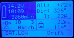
ArduPlane , ArduCopter (and similar Ardupilot projects) use Mavlink for telemetry, while Graupner has a very useful telemetry system HoTT.
This device provides all the data Graupner’s EAM(Electric Air Module),GAM(General Air Module),GPS,Vario modules offer.
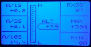
Data that Ardupilot does not provide in it’s telemetry stream: (distance and direction to home, 1s,3s,10s vario-data and battery cell voltage/min/max voltage) are calculated in the device.
ArduCopter and ArduPlane are detected automatically, and correct mode-names will be displayed.
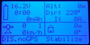
The GPS position format is converted from DD (degrees,decimals) transported by mavlink, to the DM (degrees, minutes.decimals) as expected by HoTT, direction and distance to home is also calculated, (it’s not provided by AP).
Note the “DIS.noGPS …” = Disarmed, no GPS Fix, mode is Stabilize.
This is the inverting/flashing voltage background, (also audible warning) for “Battery Low”.
Arduplane & Arducopter modes are visible as text. Future/unknown modes as number.
Real status messages:
The device enables HoTT to display actual Ardupilot system messages, longer messages are split and displayed as two interchanging parts. like this:
Bootup messages:
Should a prearm check, or arming check prevent you from arming, you will know exactly what the problem is.
This method is superior to FrSky telemetry, which at best, tries to recognize, and encode the messages, then a .lua script in the transmitter is supposed to display a corresponding/equivalent message. That method works only for known messages (depending on firmware), and things can get “lost in translation”.
This device, however, just display text as-is, and thus can display new and future messages as well as composite messages that may contain variables or debugging info.
Firmware upgrade:
There is an custom bootloader on the device, it’s possibly to upgrade it using a standard FTDI cable and the avrdude tool (exists for Linux,Mac,Windows & more).
FTDI cable, with extra pin header.
Insert pin header into FTDI cable, the protruding, short pins will fit into the Mav->Hotts six pins on the edge of the PCB.
The upper & lower of the six pins on PCB, are marked BLK (black) and GRN(green) – make sure that matches the orientation of the FTDI cable. (reversing does no damage)
To write the new firmware you will need avrdude application.
On Linux, it’s installed by: “sudo apt install avrdude”
Warning inverts/flashes the part of the display that contains battery information, and give relaxed audible warning. The LEDs, if connected, are blinking diagonally (only warning/critical state does that)
Critical battery level does the same, but the audible warning is more intense, and rapid, LEDs are flashing diagonally very fast.
Detected cell count can be seen as number of displayed cell-voltages (which is calculated from initial battery voltage)
most useful information at a glance, by using just heading, and flying so it gets equal to gearing to home – you can fly home even without seeing the model.
Mavlink mode-controlled LED controller.
There is no need for HoTT telemetry to be sent, only read the Mavlink protocol input, for the LED controller to work.
For ArduCopter, there are four outputs for leds/strips (non-amplified, so you will need a transistor if you wish to use them with more than a few LED’s)
The blinking patterns are different for each mode, but follow this system:
Stabilize = solid on
Alt-hold = short off-time on rear leds
Autopilot modes does not have solid front light, indicating that AP is on
Diagonal blinking patterns are used for errors, noGPS fix, low battery, and anything else that may be reported over 3DR radio/mavlink as an critical state.
Warning/Critical blinking ignores LED Switch function.
The outputs are on pin 7(RearLeft),8(RearRight),9(FrontRight),10(FrontLeft) . – they will flash diagonally in case of critical events, and different patterns depending on mode/situation , GPS fix and so on.
LED Switch function: if pin2 gets a PWM betwen 900…1200µs , the LEDS goes dark except if critical condition, or a battery warning – in case of which, the PWM will be ignored, and LEDs will flash anyway.
Safety:
The device does only read mavlink, (it’s connected to telemetry TX pin) , fed with power from receiver or telemetry port, and so it is unable to influence the operation of the autopilot in any way.
Connecting:
Voltage: GND and +5v goes to Pixhawk/APM or Receiver.
Connect RX pin to your 57600 baud telemetry TX pin on Pixhawk/APM
Connect Pad5 to your HoTT receiver’s telemetry input.
If you wish to power it from Pixhawk, It’s ok. This would be the connections then:
Telemetry connector(of your choice), Pin1 (red wire) – goes to VCC on the device
Telemetry connector Pin2 goes to device’s RX pin
Telemetry connector Pin6 (last one) foes to device’s GND
Pad5 on the device, is connected to you HoTT RX’s “T” input.
This is an example of a possible connection: Usually, people connect it in paralell to another Mavlink device, like OSD or radio, so there is no need to purchase a DF13 connector.
note that the device comes without wires, I assume most people do have a old servo cable, and are better off installing the length actually needed.
Troubleshooting:
If HoTT display (in the mode that display text) says NO MAVLINK … check mavlink
If you only see mode, no other info – check the parameters below, used to tell Ardupilot how often to send the different messages as suggested below:
SRx_EXT_STAT = 2 ; 2Hz battery voltage, current and capacity GPS,fix .RAW GPS position, velocity, altitude
SRx_RAW_SENS = 2 ; gives 2Hz pressure, and temperature.
SRx_POSITION =2 ; position mixed with accelerometer & barometer data
SRx_EXTRA2=2 ; heading, baro altitude, climb/descent rate
SERIALx_PROTOCOL = 1 ; set the serial/telemetry port to Mavlink protocol
A quick demo, switching between 8 modes using a servo-tester. The TAU640 in this video is set for outdoor use, and does not show the full advantage of Ice&Fire modes inside.
What you get:
A microcontroller on a small PCB (18x33x3mm) with soldering pads. Preprogrammed with 8 different modes as in this video, or up to 10 custom modes (as ordered).
The circuit works on 5v, uses less than 10mA. You can connect it using 3 wires, just like a servo)
The modes are selected using a knob on your transmitter, PWM decide mode, just like a servo position.
Serial data, is sent from the device to your FLIR device using one wire – (assuming you have common ground)
The common modes in this test video shows 8 modes I’ve found very useful.
What you need:
FLIR TAU ,TAU2, or QUARK thermal core.
For TAU, “Wearsaver” helps a lot. – It offers big soldering pads for connecting to the Hirose 50p connector. RX(pin2)
For Quark , you need to connect the serial signal to pin 15 of the Samtec 60 pin – connector. or to the breakout board, if you that.
Connection instructions:
Connect PWM (white wire) from your receiver to pad9 on PWM>FLIR device
Connect “-” (black wire) from your receiver to GND on the PWM>FLIR device
Connect “+” (red wire) from your receiver to VCC on the PWM>FLIR device
Connect pad8 on the device to your RX pad on wear saver, thats solder pad with green ring in the picture below.
Connect ground and +5v to TAU (black and red pads in picture below)
Finally, for information only:composite video out is on the yellow pad, and video ground on the blue pad on the TAU wearsaver.
Default mode configuration is:
1, white hot, no zoom , spatial threshold gain 34d.
2 white hot, 2x zoom, spatial threshold gain 34d.
3 Black Hot, no zoom , spatial threshold gain 34d.
4 Black Hot, 2x zoom, Spatial threshold = 9d
5 Fusion,no zoom, spatial threshold gain 34d.
6 ICE & Fire, no zoom, spatial threshold gain 34d.
7 Rainbow, no zoom, Spatial threshold, Gain = 34d
8 ICE & Fire, no zoom , Spatial threshold 17d
You can output a PWM from an autopilot, controlled by GCS, having any GUI you prefer. – Or , if you are will be controlling the PWM directly from a RC radio, you do not need a rotary knob with steps, it’s perfectly easy to hit desired mode even with smooth knob due to the quick visual change, and equal “distance” between modes.
Due to the proven vulnerability of current telemetry modules, I’ve developed something significantly stronger.
The source is not open, because it’s not real strong, certificate-based encryption, that allows end-user to replace, create new certificates. One advantage of doing it this way, is that you can purchase more radios and add them without having to reprogram all.
The secrets are permanently stored inside, and opening the source would give glues of possible attack vectors. I intended this to be a long time viable, secure solution.
Still – the owner have the option to get more radios that will work with his private network.
Features:
433,470,863,915Mhz support.
Fully compatible with all ground station configuration tools. All the common AT commands and parameters are there, there’s even a NetID that will let you make different networks within your encrypted network – should you wish. Example, if you have 4 CryptoTelemetry radios, you can have 3 in different UAV’s , all have the same network ID, and will speak to the same GCS, typical use is “one at a time”. Or you can set two radios with NetID different than the others, and use two GCS and two UAV simultaneously. – Note that no non-CryptoTelemetry radios will be able to communicate with these radios.
Locked down firmware, even if one malicious customer purchased it for analysis, it would be hard to learn anything from it. – Then it would take some time to find your encryption key.
Personal encryption key. (most tend to be 11digits) Only the customer will have the key, it is NOT stored here. To order more radios for the same network, it’s essential to provide the key so a properly encrypted firmware for your radio can be generated.
Your radios will operate in your network, no one else will be able to see the data, or encrypt without some extensive cryptanalysis and hacking.
Encryption can be disabled by disabling ECC – radios enter then a transparent mode, which is 2x the usual ECC data rate.
Efficient; the data rate is the the same as ECC, (half of the non-ECC speed.)
ECC (Golay24) is still active, for every 12bit , up to 3 bit errors can be corrected.
Delivered on standard, authentic, genuine 3DR telemetry radios.
If customer provides radios, it can be flashed onto a several other/compatible radios.
Reversible – should this method be obsolete one day, it is fully possible to convert these radios to run official 3DR provided firmware.
I am using this firmware for all my commercial operations as well as hobby flights, it is well tested.
Get your radio reprogrammed with CryptoTelemetry ($85):
Buy new original 3DR Radio with CryptoTelemetry ($135):
My professional background is network and Internet security, I quickly discovered the huge risk of an hostile takeover of UAV midair.
My experiment is based on 3DRobotics telemetry radios. but works with many more radios, based on the same, open, solution.
Please note that this is not a security risk of Ardupilot project, ArduCopter, ArduPlane is *not* to blame. You may get an idea that some changes should not be allowed while armed, but that’s not a proper solution. Having all the options we have, after all, GCS is a device to be trusted, and the primary control during a auto mission.
Radios lack proper security, mostly due to limited processing power for proper encryption. We are left with an simple attempt to secure the data, which is very easily worked around.
The open nature of the project, makes it impossible to truly protect the transmitted data. The radios do not have space & processing power to use public&private certificate based verification of data, also we would need a simple and a method of letting users selv-sign/generate such certificates for as many radios they needed in a network.
The current attempt to secure the transmission is based on radios dropping packets branded with different NetID- and the frequency hopping pattern to be seeded by the NetID.
So knowing or guessing one UAV’s (or companies) NetID, (provided it’s even changed from the default one) , enables anyone to send packets that are perfectly valid on the network.
To verify the theory, I needed an experiment:
I created a specialy crafted firmware for the stock telemetry radio, it proved to be a trivial task, Let’s call the module for BlackSheep, it have the following features:
Automatic sniffing of nearby NetID (as we know, the user-set NetID is also used to seed the frequency hopping)
When it finds valid packet with NetID, it learns active frequencies, and changes it’s frequency hopping to the pattern of that particular NetID – locking in on it. – whole process takes ~1second.
By connecting BlackSheep to any GCS, we have instantly a valid connection to a nearby operating UAV.
Hijacking the drone in real life.
We can assume a low-tech drone hijacker would do it by running a GCS and just do it manually. An intermediate hacker would use scripts with MavProxy, or clicking around in GCS software – but the optimal solution, is a predefined set of commands used by a modified GCS for easy map interaction.:
This is what an takeover looks like;
pointlessly evil hijacker could just disarm the drone midair or send MAV_CMD_DO_FLIGHTTERMINATION – but that’s not the goal here.
send, and repeat a few times: SR?_* = 0 – disables all telemetry output from AP , make the radio go silent. This will also reduce amount of packet collisions if we have 3 radios operating. (UAV is the one occupying most of the radio time) – now the victim GCS operator does not get any more updates.
Then we set all control FLIGHTMODE_? to AUTO or Guided (by preference), and disable FS_Throttle and FS_GCS , CH6 and other programmable options are disabled. The pilot with RC can’t do anything anymore.
Enabling SR?_EXT_STAT – gives the hijacker RAW GPS data, altitude, speed – this data is usually not visible on a GCS, so the victim can’t see it – but hijacker knows where the UAV is.
Uploading a mission, or Guided mode instructions sends the UAV to wherever hijacker wants – victim have no valid input, and cannot see it in GCS, all he gets is Mavlink heartbeat.
Finally, for the extra evil touch hijacker can inject Mavlink MAVLINK_MSG_ID_GLOBAL_POSITION_INT packets (as if autopilot was sending it) with proportionally incorrect data, so we could get the victims GCS display and log the real movement, with actual speed, but in different direction, misguiding as to where the UAV went.
I skipped a few trivial steps, like setting higher cruise-speed, and few platform dependent commands – but the short summary should be frightening enough.
What can be done to prevent such hijacking ?
Fly without telemetry radio, reducing mission control and control redundancy, not good.
Use cellular network to get TCP or UDP control, limited coverage.
Use wifi, very poor range.
Satellite modem, expensive, very low data rate, often ~2400bps
Continue to develop open solutions with hardware limitations that limits us to very simple security solutions, like the one in use today – very easy to circumvent.
Use customized, specialized, closed solution that offers good security, it is not proper certificate based encryption, but rather an odd, but very effective scrambling. Effective mostly because the firmware is locked down, and not easy to analyze.
Final words:
Telemetry radios , 433/900Mhz are great, most aviation authority approved approved flights , professional or hobby, are within VLOS, where these radios perform great.
The fact the source i open, is not a drawback, but a strength. It allows people like me to detect security vulnerabilities, like many other can do, and documents them, or protect against them, so others cannot silently abuse them, without users understanding what’s going on.