How to locate SMBUS
on motherboards with no SMBUS header


After publishing the additional fan and temperature sensors projects, I've received many questions from people that did not find / do not have an SMBUS header on their motherboard.
Motherboards SMBus connector is 5(4)-pin
and is configured like this:
1-CLOCK
2-not used (this pin is removed for keying
purposes)
3-GND
4-DATA
5-+5Volt
Everybody should
know, that every Pentium and newer motherboard
does have an SMBUS, that means the bus, as an electrical circuit, and at least one master device (usually
southbridge) and few slave devices (temp sensors, voltage sensors, rpm
sensors, and misc. ROM , PROM, EPROM or
EEPROM)
- even XBOX does have an SMBUS.
If your motherboard does not have an SMBUS connector this means the maker just saved less than 10 cents by not mounting an 5 pin header. (same sort as jumpers uses)
One option is to find another monitoring chip on the motherboard, get it's datasheet, and connect to the pins. - I cannot describe it as it vary from MB to MB.
However, all modern RAM is equipped with some sort of memory (ROM...EEPROM) where the timing-tables are stored, this allows the motherboard(/BIOS) to detect what timing the RAM require/can handle. (and a lot of other stuff too)
These ROM's are always connected to SMBUS, and the device can be recognized by it's small size (usually 8 pin SO8 chip)
.. so you can connect to your RAM in order to get connected to the SMBUS.

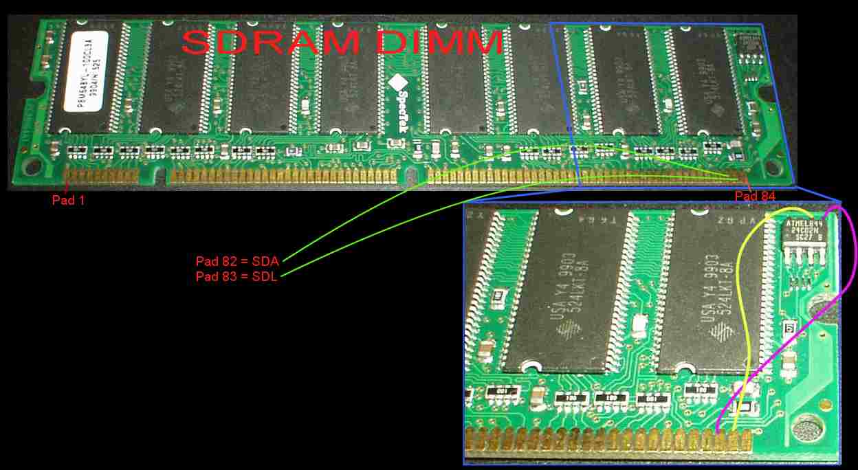
(Download picture for better quality/zooming)
The pad number 82 is SDA and 83 is SDL, the thin green
lines in the picture shows their location.
The next step is to find out where pad 82
and 83 is connected to. (because you cannot
solder directly on the pads for obvious reasons :)
You should find (using an multimeter) which of the 8 pins are connected
to pad 82 and which to pad 83
The EPROM on this particular RAM DIMM is an ATMEL 844, 24C02N , and the purple line shows that SDA goes to pin 5 on the SO8 chip , while the SDL (yellow) have been traced to pin 9
This is how you find SMBUS on your RAM DIMM
Same story, except for few differences:
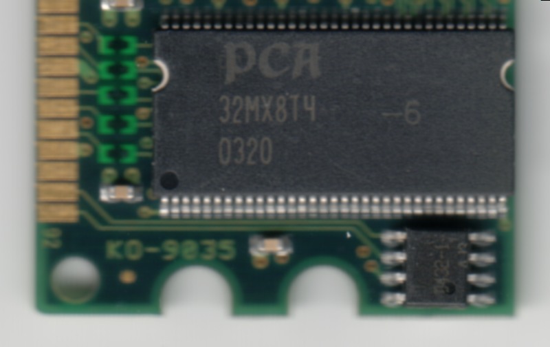
RAM's "front side" : Pad1 (on the left) pad 92 to
the right
PAD 91=SDA
PAD 92=SCL

this picture shows pads 91 & 92 (92 is marked) - and the stright lines to the EPROM
-You should get the +5volt and GND from the floppy or HD power
connector.
-You should NOT have a circuit connected to SMBUS without that circuit
being connected to GND.
-You may solder directly on DIMM pads, (if you are skilled), you can
solder thin wires on the upper part of the pads only. - and the RAM
will still fit.
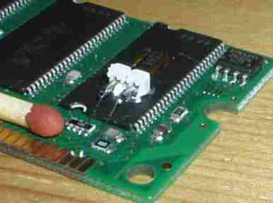
Example: I hot-glued a 2.54mm pin header to one
of the RAM IC's, then soldered this wires (parts of one of the wires in
a floppy connector) between the pads and the pin-header.

Ian - For telling me that some Gigabyte motherboards (at least Gigabyte 8KNXP) have some propietary SMBUS connector, the header is called "INFO_LINK" , and is a 2x5pin header with pin 7 removed (for keying)
| Pin | Signal |
| 1 | SMBCLK |
| 2 | VCC (5V) |
| 3 | SMBDATA |
| 4 | GPIO |
| 5 | GND |
| 6 | GND |
| 7 | (no pin) |
| 8 | NC |
| 9 | +12V |
| 10 | +12V |
Per Ullman - shows you here
how he build the fan-sensor project and connected it to the RAM DIMM
sockets (on the solder side of the motherboard), rather than soldering
directly on the DIMM'S.
(He also reminds you that any plain "multimeter" can help you tracing
where those signals can be found on the opposite side of the
motherboard)
Daniel - for sending the picture of an DDR-2700 RAM, that shows pad 91&92
Q: does IR/Comm/Serial header work as SMBUS ?
(actual frequent question)
A: NO. SMBUS is SMBUS or it could be labelled as I2C (I've never
seen it being called I2C in computer world, even it's exactly the same thing.)