If it’s worth doing, it’s worth overdoing. I started with interpreting what they said , It sounded to me like this: “30Watts are OK , I have it because I could not afford the 50Watts , anything over 50Watts is what I would like to have”
So… what I “needed” was :
- 225Watts … (3 x75Watt bulbs)

- battery time of at least two hour at reasonably high intensity…
- Variable intensity
- >20Khz PWM (Pulse Width Modulation) to keep high efficiency and no noise.
- Internal 28Volt DC-DC converter to improve efficiency of Power MOSFET’s .
- Multiple bulbs (3), just in case one dies – there are still two left.
- Voltage monitoring.
- No disassembly required for charging.
- Nice software with SOS and maybe a bottom-timer.
- Self adjusting intensity (not implemented yet)
- Low battery warning and battery capacity prediction. (not done yet)
So , the project resulted in:
Acrylics pipes with 22mm acrylics ends , with O-rings , 4Mhz RISC Microprocessor that works at 4-5 volts , 28Volt DC-DC pump , 2 optically isolated PWM outputs that uses the 28volts to control 50Ampére low-drop power MOS-FET’s so fast that the MOSFET’s does not require any cooling as they “never” are in linear state. A 2×16 Character LCD display had to be added.
There are no moving parts, the 3 buttons and on/off are magnetically controlled and does not represent a weak point (or should I say leak point ?) ![]()
here is the battery case : two 12Volt 6,5Ah batteries in parallel gives 13Ah ! (could be 2×7.2Ah , but I 6.5Ah was all I had).
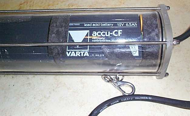
Here is the torch , 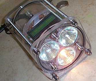
the display is showing voltage and intensity. as soon one bulb is 100% on , the other 2 starts helping , that’s to distribute the bulb-burn-time so their life length will be different. those are 3x50Watts “Osram Decostar” (1×10º , and 2×24º) halogen bulbs ,just because I did not got any 75Watts , of course , the electronics will handle 3x75W (225Watt)
The LCD display is back-lit , (green/blue) , and looks very nice under water. Now booting …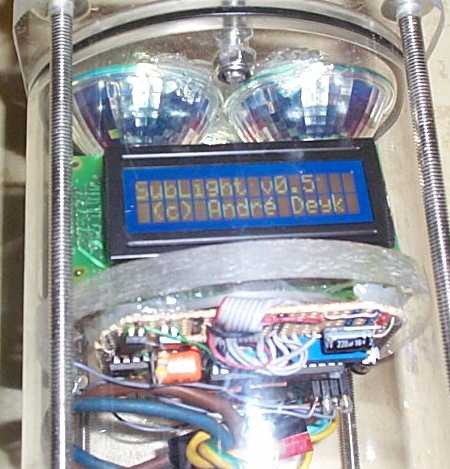
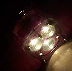 because of the massive intensity of the light , the camera could not do better , the LCD is invisible , It’s normal daylight in the room but “seeing” this bright light source , the camera made this picture so dark.
The Freeware
The design/circuit should always be treated as freeware, you might build as many as you like , even for your friends.
The author (me) must always be credited as the author.
The compiled program is here. , It is possible to buy preprogrammed controller from me.
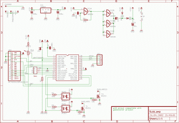
The schematics: (right click the picture below and “save target as”)
A little description , it should be everything you need to know:
- U$3 is the LCD connector , any HD44780 compatible LCD goes , at least 2×16 characters.
- PADLAMP1 is the pad (output) for lamp1 , padlamp23 is is for lamp 2and3
- JP2 is the switch/button connector
- use IRFZ44 or better power MOSFET (BUZ 11 is used on schematics by accident) – they are pin-compatible.
FAQ:
Q: Do you have the container plans ?
A: No ,I just found some material that would fit the batteries worked on it.
Q: Is there a PCB layout ?
A: Yes , I designed a two layer PCB ,but never etched it.
Q: Where did you found the O-Rings you needed ?
A: A hardware store sold them as meter-ware with a special glue, then I made the O-rings I needed.
